Technical & Electrical Specifications
- Main Processor: 40 MHz 32-bit PowerPC RISC CPU with integrated hardware floating-point arithmetic unit
- Onboard Memory: 4 MB Flash EEPROM program storage, 4 MB volatile RAM real-time data buffer
- Analog Input Channels: 8 channels 16-bit resolution, signal range ±10 V / ±10 mA / 4–20 mA universal compatibility
- Analog Output Channels: 2 channels 16-bit resolution ±10 V servo valve drive output
- Encoder Feedback Interface: Differential line-drive encoder input for dual-axis position feedback
- Communication Interfaces: CAN/CANopen, RS-232 serial, 10/100 Mbps Ethernet, optional Profibus-DP expansion slot
- Minimum Control Loop Cycle Time: 100 μs dual-axis synchronous closed-loop calculation
- Rated Supply Voltage: 24 VDC industrial control power
- Operating Temperature Range: 0 °C to +55 °C
- Enclosure Protection Grade: IP20 for indoor cabinet installation
Functional Features
- Native hydraulic servo algorithm library including flow compensation, pressure feedforward and friction deadband elimination subroutines
- Embedded full-function PLC ladder logic runtime eliminating separate auxiliary PLC hardware
- Independent dual-axis control channel with fully decoupled parameter configuration
- Real-time force limiting protection function to prevent mechanical overload equipment damage
- Built-in system diagnostic module recording servo valve drift, encoder signal loss and power supply fluctuation fault logs
- Ethernet-based remote programming, real-time data monitoring and fault history download support
- Configurable safety enable signal threshold (enable active above +8.5 VDC, disable below +6.5 VDC)
Working Principle
24VDC input power supplies isolated multi-stage DC-DC power conversion circuits for CPU, analog signal acquisition and communication modules. Differential encoder position signals from hydraulic cylinder linear transducers enter high-speed counter peripheral circuits to convert analog position displacement into digital coordinate data. The PowerPC CPU executes real-time closed-loop PID hydraulic control algorithm combining position setpoint command, actual position feedback and pressure force feedback signals, outputs calibrated ±10 V analog drive signals to MOOG servo valves. Embedded PLC logic processes digital interlock safety signals, synchronizes axis movement sequence and triggers emergency stop upon safety circuit break. All operating data transmits to upper HMI or DCS via CANopen/Ethernet bus.
Material Composition
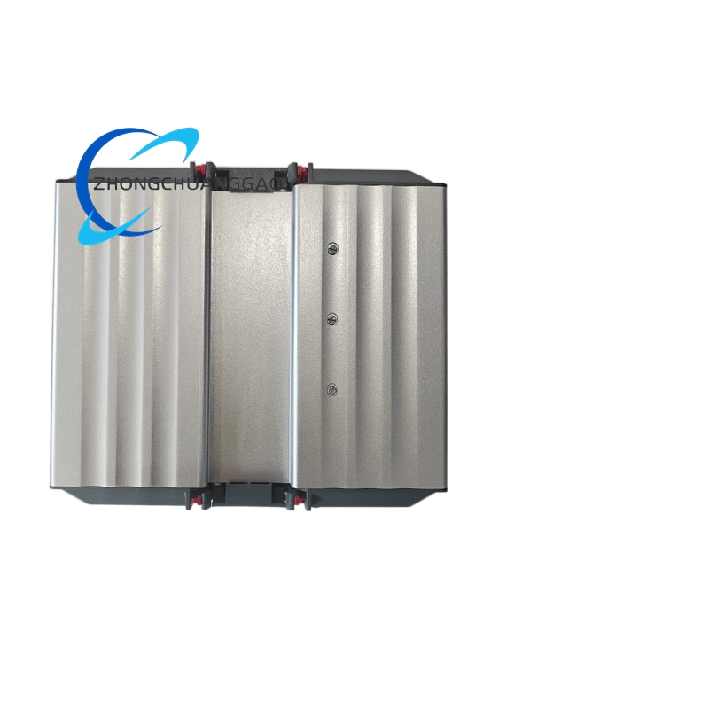
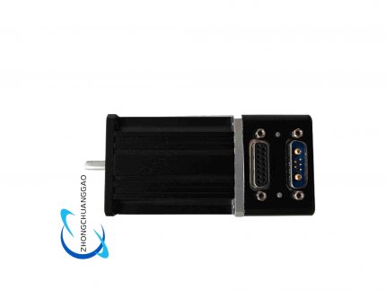
- Main Housing: Black extruded aluminum alloy front heat sink frame, UL94-V0 ABS plastic terminal cover
- Control PCB: Multi-layer FR4 PCB with gold-plated signal traces for low signal attenuation
- Terminal Blocks: Spring-clamp nickel-plated copper screw terminals supporting wire cross-section up to 2.5 mm²
- Heat Dissipation Medium: Vertical ribbed aluminum extrusion heat sink integrated with main housing
Structural Characteristics
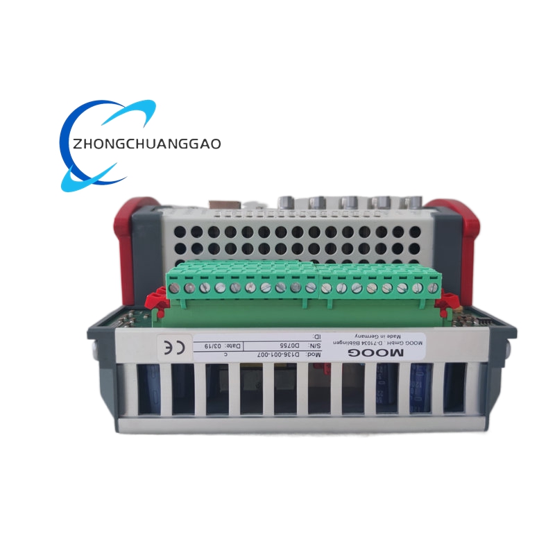
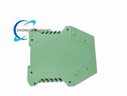
- Modular vertical stacking DIN 35 mm rail mounting design
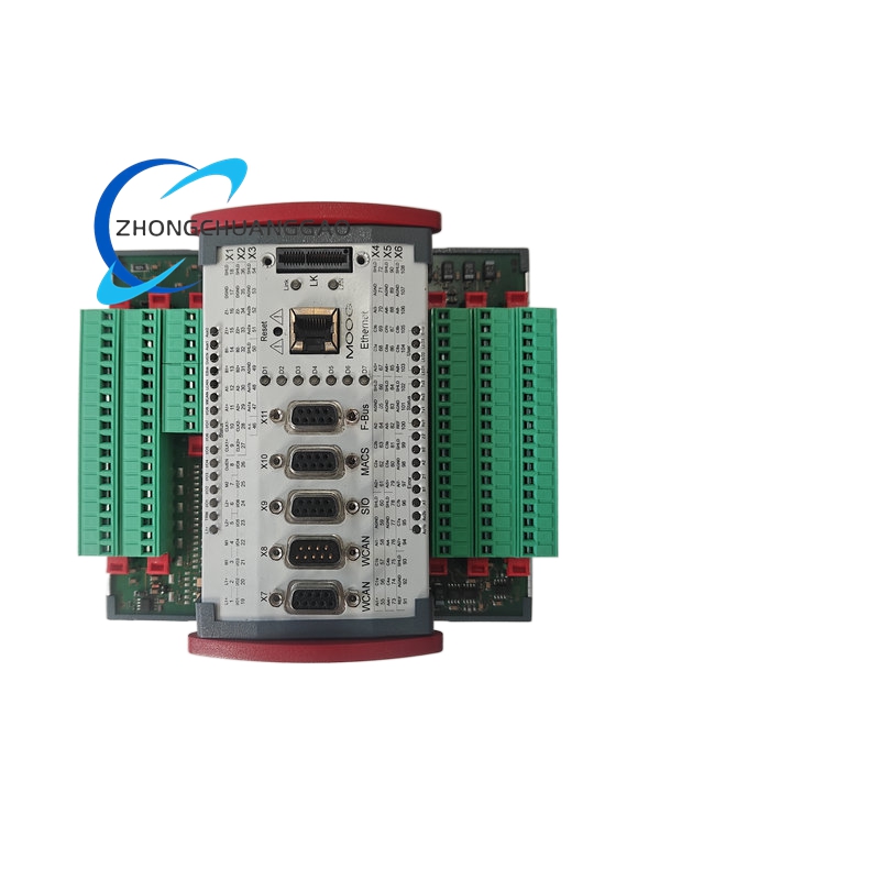
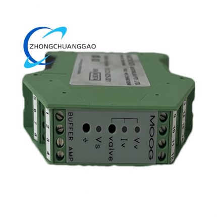
- Front panel segmented terminal layout: upper analog I/O terminals, middle communication ports, lower safety digital interlock terminals
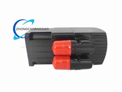
- Side red plastic locking latches for vibration-resistant DIN rail fixation
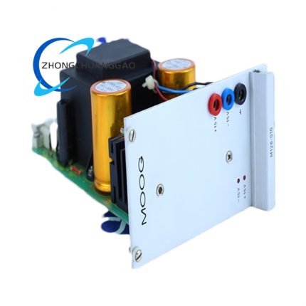
- Front panel status LED group: power run, communication link, axis fault, safety enable alarm indicators
- Separate shielded metal partition isolating analog high-precision signal zone from digital high-speed communication zone
Advantage Highlights
- Microsecond-level dual-axis synchronous control cycle unmatched for high dynamic hydraulic test equipment
- Integrated PLC and motion control single hardware unit reduces cabinet component count by 60%
- 16-bit high-resolution analog drive outputs ensure ultra-linear servo valve flow regulation
- Multi-bus communication compatibility supporting seamless connection with mainstream industrial upper control systems
- Factory pre-calibrated hydraulic algorithm library cuts on-site commissioning time by over 70%
- Hardware-isolated analog signal circuits eliminating cross-talk interference between dual-axis channels
Applicable Industries
Aerospace flight simulation systems, metal stamping & hydroforming presses, power generation steam turbine DEH control, automotive component fatigue hydraulic test benches, precision injection molding hydraulic control
Installation Requirements
- Install inside IP54 or higher industrial electrical cabinet, vertical DIN rail mounting orientation
- Maintain minimum 30 mm vertical clearance top and bottom for aluminum heat sink natural convection
- Analog signal wiring use individually shielded twisted pair cables, single-point grounding at controller terminal block
- Separate 24VDC power supply dedicated to controller, do not share power circuit with high-current relay loads
- Communication Ethernet/CAN bus cables route isolated from analog servo valve drive wiring
Usage Precautions
- Strictly prohibit operation when cabinet ambient temperature exceeds +55 °C to avoid CPU thermal throttling
- Conduct quarterly encoder signal cable insulation resistance inspection to prevent position feedback drift
- All analog signal cable shielding must connect to controller ground terminal only, floating at sensor end
- Backup Flash EEPROM program data before firmware upgrade operation
- Do not remove analog terminal block while controller is powered to avoid transient signal spike damaging internal ADC chips




























Reviews
There are no reviews yet.