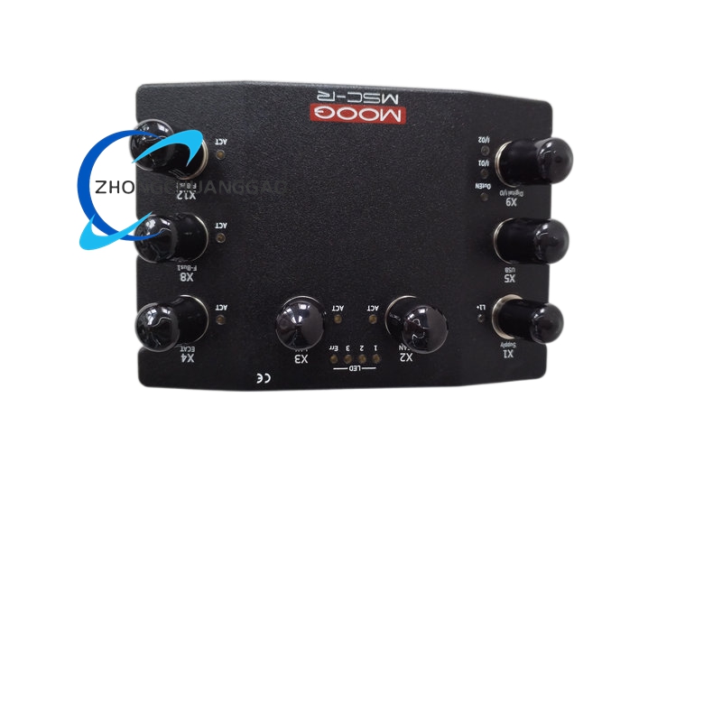
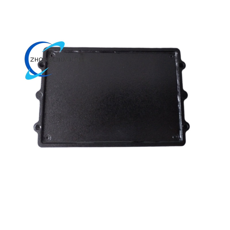
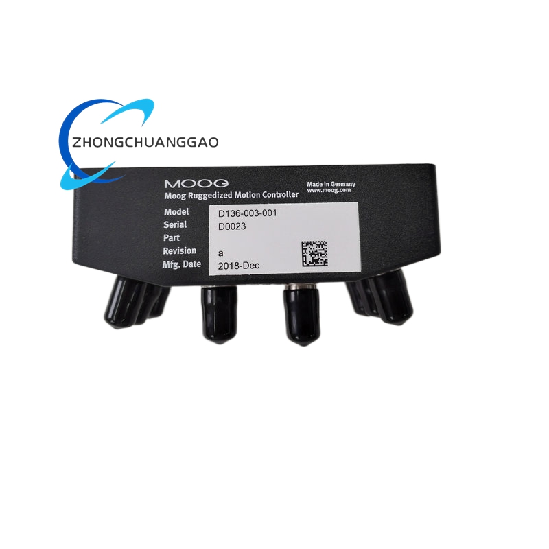
Technical & Electrical Specifications
- Main Processor: 40 MHz 32-bit PowerPC RISC CPU with hardware floating-point unit
- Onboard Memory: 4 MB Flash EEPROM, 4 MB real-time RAM buffer
- Analog Input Channels: 4 channels 16-bit resolution universal ±10 V / ±10 mA / 4–20 mA signal
- Analog Output Channels: 1 channel 16-bit ±10 V servo valve drive output
- Encoder Interface: Single differential line-drive position feedback channel
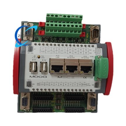
- Communication Ports: CAN/CANopen, RS-232, Ethernet, optional Profibus expansion
- Minimum Closed-Loop Cycle Time: 80 μs single-axis independent control loop
- Supply Voltage: 24 VDC industrial control power
- Operating Temperature: 0 °C to +55 °C, IP20 cabinet-only installation
Functional Features
- Full MOOG proprietary hydraulic servo control algorithm suite optimized for single actuator response
- Lightweight embedded PLC runtime for basic digital safety interlock logic
- Single-channel independent force overload protection with configurable trigger threshold
- Integrated servo valve null drift real-time compensation subroutine
- Compact fault logging storage recording valve drive circuit, encoder and power supply abnormal states
- Ethernet remote parameter upload/download and real-time axis monitoring
- Hardware safety enable circuit matching MSC I series unified signal standard (8.5 VDC active threshold)
Working Principle
Identical core power conversion and signal processing architecture to D136-001-007; single-axis encoder position feedback and single analog servo drive channel replace dual-axis hardware circuit layout. CPU executes single-axis position-velocity-pressure three-loop closed-loop algorithm, outputs calibrated analog command signal to single hydraulic servo valve. Simplified PLC logic processes safety interlock signals for single actuator emergency stop and position limit protection, transmits real-time operating data via industrial fieldbus to upper monitoring system.
Material Composition
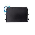
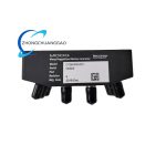
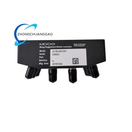
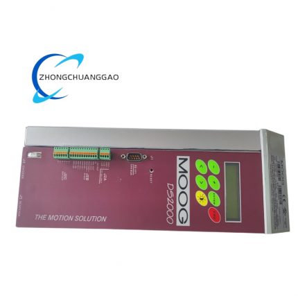
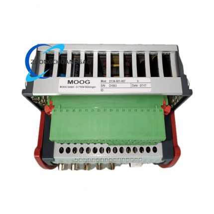
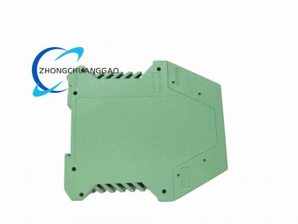
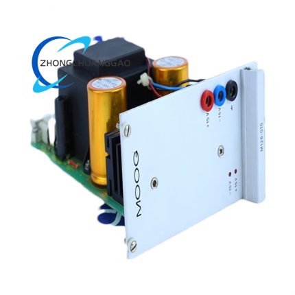
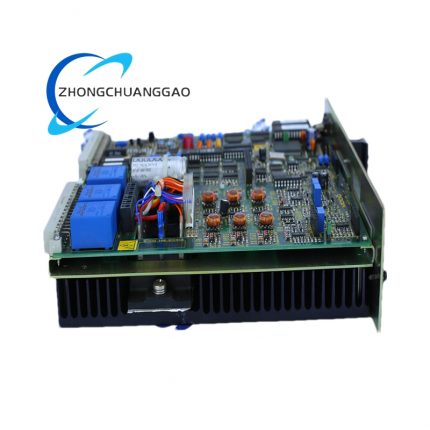
- Housing: Miniaturized ribbed aluminum alloy front heat sink, UL94-V0 ABS plastic terminal cover
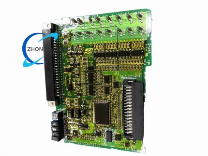
- PCB: Double-sided high-density FR4 gold-plated signal board
- Terminals: Spring-clamp nickel copper screw terminals for 0.5–2.5 mm² wire cross-section
Structural Characteristics
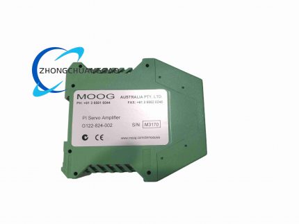
- Narrow-body DIN 35 mm rail single-module mounting, reduced width compared to dual-axis D136-001-007
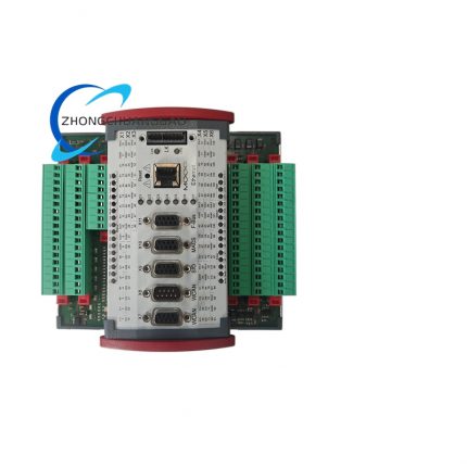
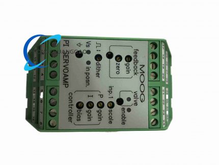
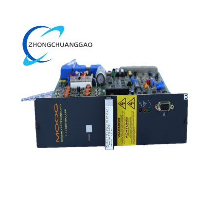
- Front panel compact terminal grouping: single encoder feedback terminal group, single analog output terminal group, digital safety terminals
- Integrated side anti-vibration red plastic DIN rail locking buckles
- Simplified front LED indicator matrix including power, run, axis fault and safety enable status lights
Advantage Highlights
- Narrow body size saves 35% cabinet installation space versus dual-axis controller variant
- Lower power consumption due to removed redundant dual-axis signal processing circuits
- Identical control algorithm compatibility with D136 dual-axis model for unified engineering configuration standards
- Simplified wiring layout reducing on-site cable quantity and wiring labor cost
- Lower procurement cost for single-station independent hydraulic control applications
Applicable Industries
Single-station hydraulic material test rigs, small precision extrusion machinery, single-cylinder mold position adjustment equipment, laboratory hydraulic load simulation benches
Installation Requirements
- Standard vertical DIN 35 mm rail cabinet installation, minimum 20 mm vertical clearance for heat dissipation
- Dedicated isolated 24VDC power supply separate from high-current relay and solenoid loads
- Shielded twisted pair cabling mandatory for analog servo valve drive and encoder feedback wiring
Usage Precautions
- Not compatible with dual-axis synchronous motion control systems; select D136-001-007 for multi-axis coordinated movement
- Avoid co-locating analog signal wiring adjacent to high-frequency AC inverter power cables
- Conduct semi-annual encoder wiring continuity and insulation resistance testing
Reviews
There are no reviews yet.