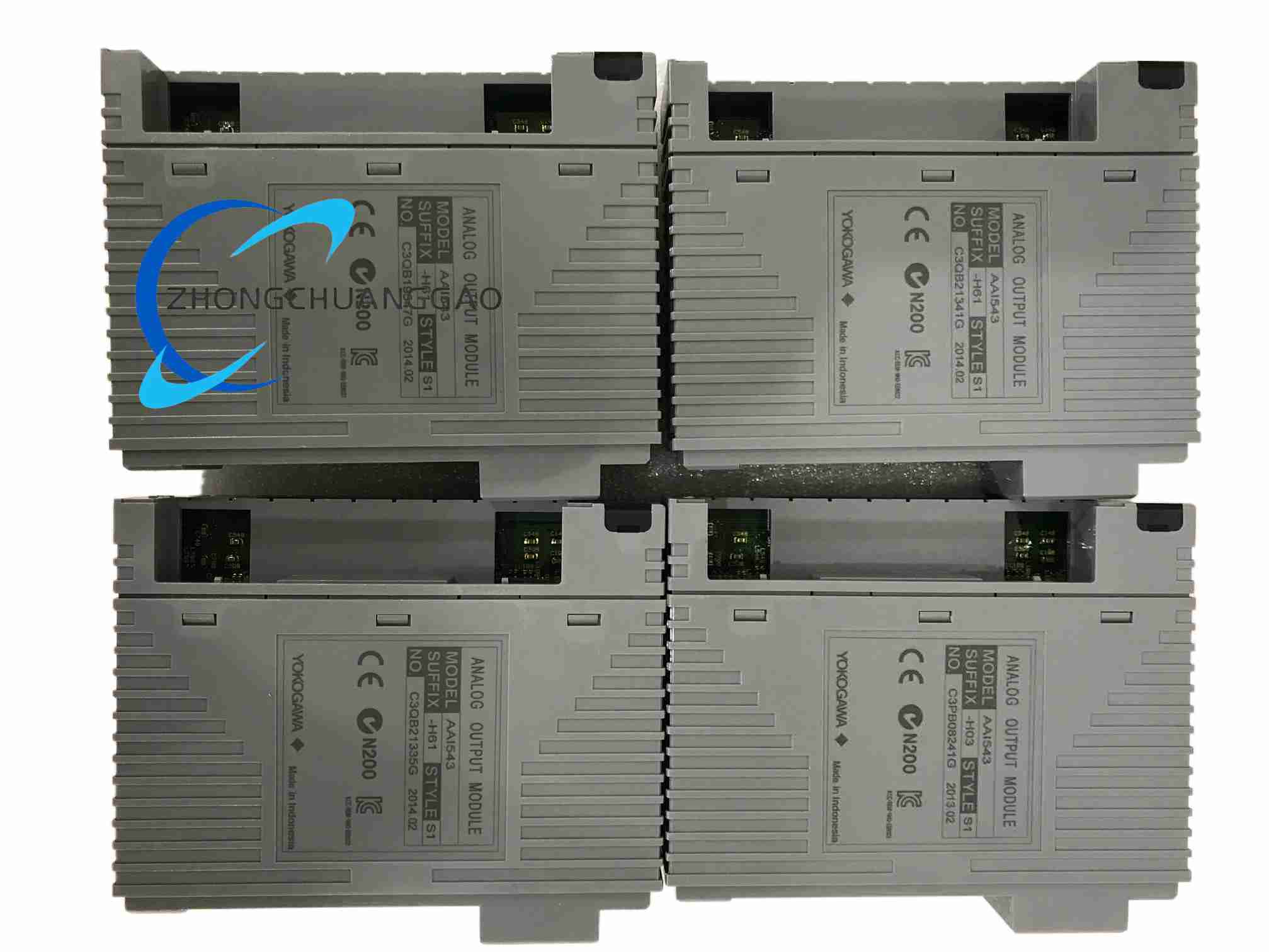
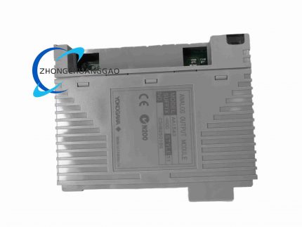
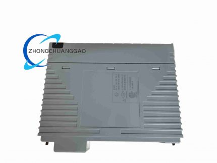
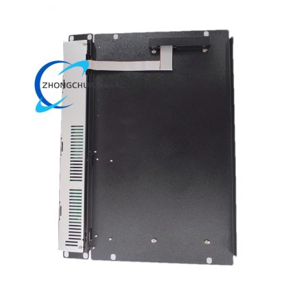
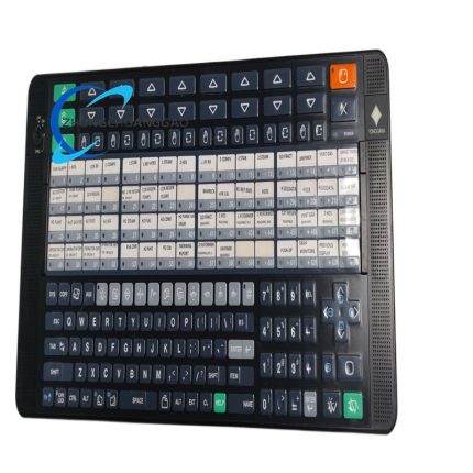
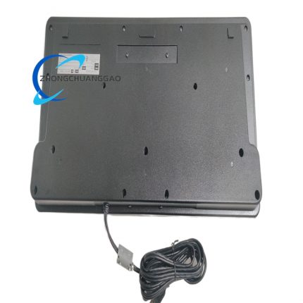
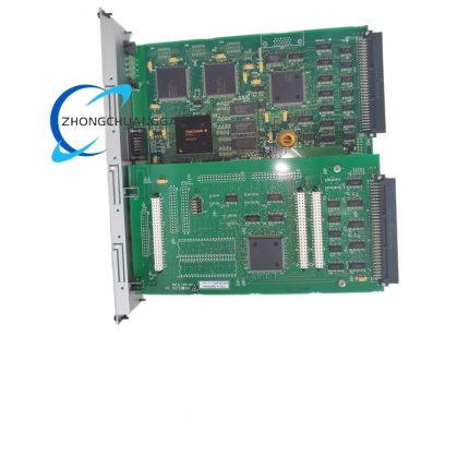
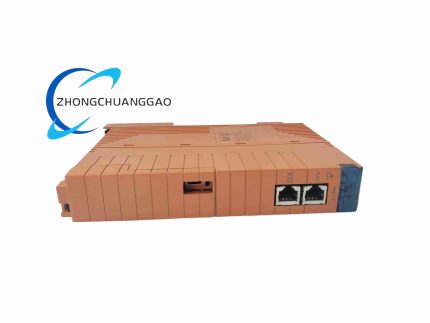
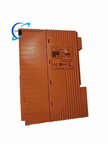
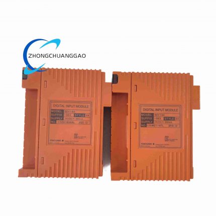
YOKOGAWA AAI543-H61-K4A00

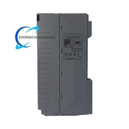
Product Introduction The AAI543-H61/K4A00 is a dual-redundant-capable 16-channel analog current output module for the Yokogawa CENTUM VP DCS. The H61 revision supports hot-standby dual-redundant I/O configurations, enabling bumpless switchover between paired modules for high-availability process control. The /K4A00 style code specifies pressure-clamp terminal block connections for tool-free, vibration-resistant field wiring. The module delivers 4 to 20 mA outputs with full HART protocol communication on every channel.

Category:
Description

Technical Specifications Output Channels: 16 channels, fully galvanically isolated Output Signal: 4 to 20 mA DC Digital Communication: HART protocol, bidirectional overlay Redundancy: dual-redundant hot-standby configuration supported (H61 revision) Output Accuracy: ±0.1% of span Allowable Load Resistance: 0 to 750 Ω Data Update Period: 10 ms Withstand Voltage: 1500 V AC between output and system, 1 minute Operating Temperature: 0 to +55 °C Storage Temperature: -40 to +70 °C Power Supply: 24 V DC ±10% (field side) Terminal Style: pressure-clamp (K4A00 suffix) Mounting: FIO I/O system rack

Functional Features Dual-redundant architecture provides continuous output during module failure or maintenance, with bumpless switchover and no process interruption. Sixteen isolated channels prevent cross-channel interference. HART protocol enables remote device configuration, multi-variable reading, and predictive maintenance data collection from smart field devices. Pressure-clamp terminals accept solid or ferruled wire without screwdrivers, reducing installation time and improving vibration resistance.

Application Scenarios High-availability process control in refineries, offshore platforms, chemical plants, nuclear auxiliary systems, and large-scale power generation where single-point failure is unacceptable. Drives critical control valves, emergency shutdown valves, and regulated drives requiring continuous output integrity and HART diagnostics.

Performance Parameters Output resolution: 16-bit Accuracy: ±0.1% of span Temperature drift: ±16 µA per 10 °C Switchover time: bumpless, no output glitch during redundancy transfer Isolation voltage: 1500 V AC Update period: 10 ms Humidity range: 5 to 95% RH non-condensing

Material Composition UL 94 V-0 flame-retardant polymer housing. Gold-plated backplane and terminal contacts. Glass-fiber reinforced PCB. Internal isolation transformers and optoelectronic isolators. Steel EMI shielding enclosure.

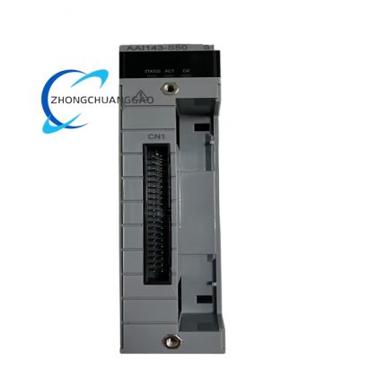
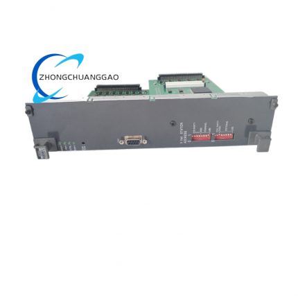
Structural Features Single-slot plug-in module with redundant-pair mating capability. Front panel includes channel status LEDs, HART activity indicators, and a module-fault LED. Pressure-clamp terminal block accepts 0.2 to 2.5 mm² wire. Internal circuitry features per-channel DC-DC isolation and precision current sources. Rear backplane connector carries ESB bus signals, power, and redundancy synchronization lines.

Working Principle In redundant operation, two identical modules are paired: one is active and drives the output, the other is in hot-standby and continuously tracks the active output value. The FCS sends setpoint data to both modules simultaneously. If the active module detects an internal fault or is removed, the standby module takes over within the bumpless switchover window, maintaining the exact output current without a step change. HART FSK signals are modulated onto the 4 to 20 mA loop for digital communication with field devices.

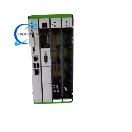
Installation Requirements Install redundant pairs in adjacent slots within the same FIO node rack. Configure redundancy parameters through the CENTUM engineering software before commissioning. Use pressure-clamp terminals: insert ferruled or solid wire into the terminal port and confirm the clamp engages fully. Verify all field wiring is de-energized during initial installation. Maintain 0 to 750 Ω load per channel. Ensure rack cooling and ambient temperature meet specifications.

Usage Precautions Always configure and test redundancy switchover during commissioning before placing the loop into automatic control. Do not mix H61 redundant modules with non-redundant S00 modules in the same redundant pair. Keep HART loop wiring separated from AC power cables. Use shielded cable and single-point grounding. Before replacing a module, place the corresponding control loop in manual or transfer output to the partner module. Do not apply voltage to output terminals externally.

Reviews (0)

Reviews

There are no reviews yet.

Be the first to review “YOKOGAWA AAI543-H61-K4A00”

Your email address will not be published. Required fields are marked *

Shipping and Delivery

MAECENAS IACULIS

Vestibulum curae torquent diam diam commodo parturient penatibus nunc dui adipiscing convallis bulum parturient suspendisse parturient a.Parturient in parturient scelerisque nibh lectus quam a natoque adipiscing a vestibulum hendrerit et pharetra fames nunc natoque dui.

ADIPISCING CONVALLIS BULUM

  • Vestibulum penatibus nunc dui adipiscing convallis bulum parturient suspendisse.
  • Abitur parturient praesent lectus quam a natoque adipiscing a vestibulum hendre.
  • Diam parturient dictumst parturient scelerisque nibh lectus.

Scelerisque adipiscing bibendum sem vestibulum et in a a a purus lectus faucibus lobortis tincidunt purus lectus nisl class eros.Condimentum a et ullamcorper dictumst mus et tristique elementum nam inceptos hac parturient scelerisque vestibulum amet elit ut volutpat.