Technical Specifications
- Mounting Standard: Vertical DIN 35 mm top hat rail mounting
- Overall Dimensions (W × H × D): 60 mm × 180 mm × 145 mm
- Net Unit Weight: 0.78 kg
- Main Power Input: Single-phase AC 100–240 V, 50/60 Hz
- Control Circuit Auxiliary Power: 24 V DC ±10%
- Continuous Output Rated Current: 10 A RMS
- Peak Overload Output Current: 25 A RMS, sustain duration 3 seconds
- Control Loop Architecture: Triple closed-loop (current / velocity / position) hardware real-time control
- Encoder Feedback Supported Types: Incremental TTL encoder, Sin/Cos encoder, single-turn absolute encoder
- Pulse Command Input Modes: Differential line driver pulse/direction, CW/CCW pulse train
- Industrial Fieldbus Interfaces: Modbus RTU RS485, CANopen DS402 motion protocol
- Onboard Digital I/O: 8 isolated digital inputs, 4 isolated digital outputs
- PWM Switching Frequency: Fixed 16 kHz
- Position Control Resolution: 32-bit floating-point position register
- Operating Ambient Temperature: 0 °C to +50 °C
- Storage Temperature Band: -30 °C to +75 °C
- Relative Humidity Range: 5%–95% RH, non-condensing
- Isolation Voltage Rating: 2000 V AC between power circuit and signal control circuit
- Compliance Certifications: CE EMC, UL safety standard
Function Features
- Hardware triple closed-loop control delivers ultra-fast dynamic response for high-speed positioning tasks
- Built-in auto-tune algorithm automatically matches motor electrical parameters for commissioning without manual calculation
- Multiple position command reception modes support pulse control from external PLC and bus motion command via CANopen
- Electronic gearbox and position soft limit logic pre-programmed in drive firmware
- Full-channel isolated digital I/O for home sensor, limit switch, brake output and fault alarm signal transmission
- Dynamic braking circuit integrated inside unit for rapid motor deceleration during emergency stop events
- Real-time motor overload, overvoltage, undervoltage, overheat and encoder disconnection fault detection with code storage
- Built-in electronic cam curve storage for repetitive synchronous positioning cycles without upper controller intervention
Performance Parameters
- Current loop response bandwidth: 3000 Hz
- Velocity loop response bandwidth: 1200 Hz
- Position loop response bandwidth: 400 Hz
- Minimum position command pulse input frequency: 0 Hz, maximum 2 MHz differential pulse
- CANopen motion command update cycle: Minimum 1 ms
- Overheat protection trigger threshold: Internal power module temperature ≥85 °C
- Dynamic brake discharge energy capacity: 120 J single discharge cycle
- Position repeatability after homing cycle: ±1 encoder count
Material Composition
- Outer casing: Cold rolled steel sheet with black anti-rust electrostatic spraying coating
- Internal power substrate: High-temperature insulated aluminum base PCB for power IGBT module heat conduction
- Control circuit board: Double-layer FR4 flame retardant industrial PCB
- Power semiconductor components: Industrial grade IGBT power modules, fast recovery diodes
- Terminal blocks: Glass-filled PA66 thermoplastic with tin-plated copper screw terminals
- Heat dissipation parts: Aluminum alloy fin passive heat sink bonded to power substrate
- Communication connectors: Gold-plated D-Sub encoder feedback port, RS485 terminal block
Structural Characteristics
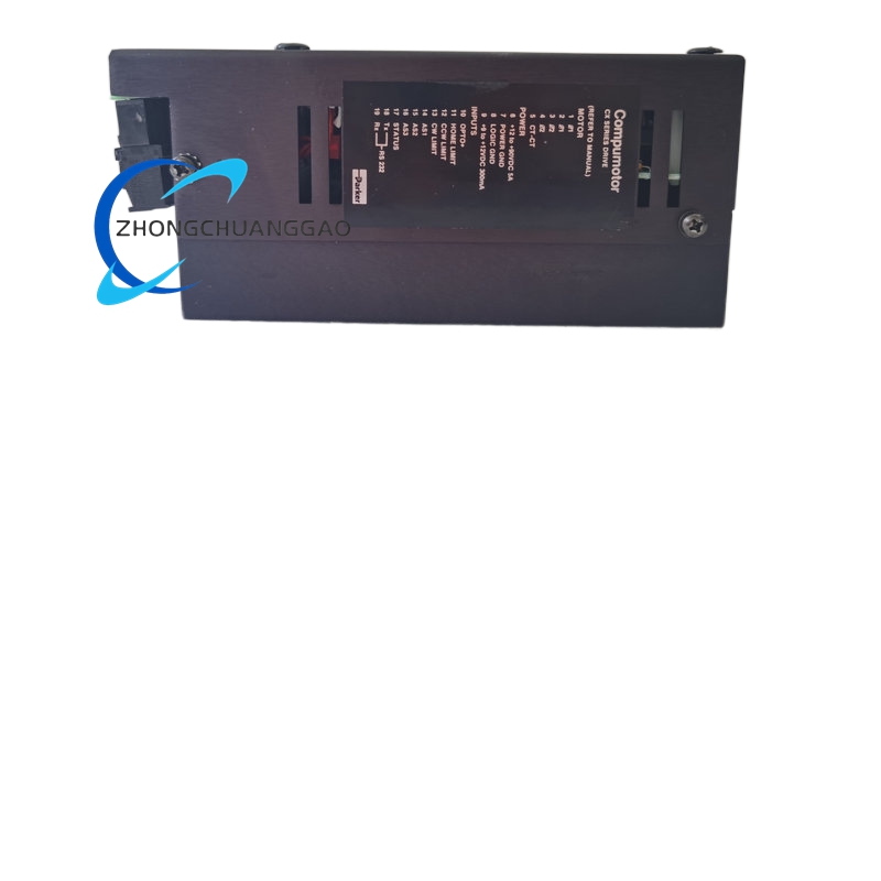
- Vertical DIN rail compact mounting structure with side metal heat sink fins exposed to cabinet air flow
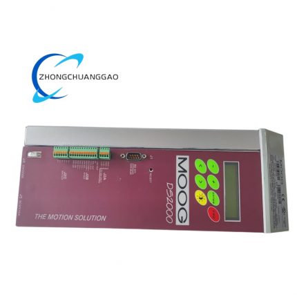
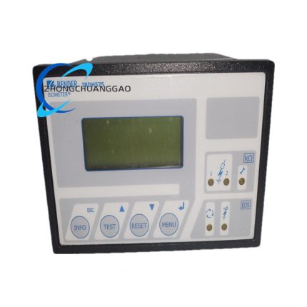
- Front panel layout: Digital parameter display screen, function operation buttons, fault status LED indicators
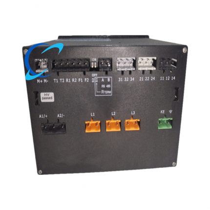
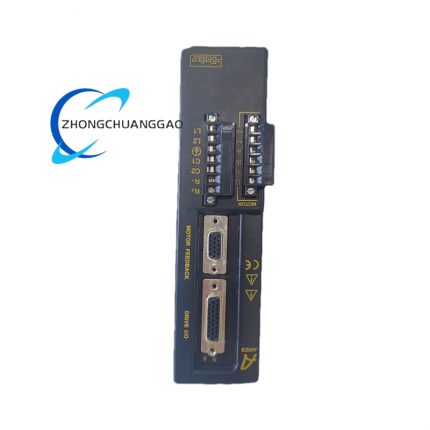
- Top terminal area: Main AC power input terminals, motor power output terminals, dynamic brake resistor connection terminals
- Bottom terminal area: 24 V control power supply, digital I/O signal terminals, encoder D-Sub port, CANopen/Modbus communication terminals
- Segmented internal layout: High-voltage power circuit zone isolated by metal barrier from low-voltage signal control zone
- IP20 overall protection rating for cabinet internal installation only
- Integrated DIN rail metal locking bracket for stable anti-vibration mounting
Working Principle
- Single-phase AC main power passes through EMI filter and rectifier circuit to convert into DC bus voltage for IGBT power inverter module
- 24 V DC auxiliary power supplies low-voltage control board, encoder feedback acquisition circuit and digital I/O isolation modules
- Current loop hardware chip samples motor phase current in real time and outputs PWM modulation signal to IGBT module to adjust output torque
- Encoder feedback circuit collects motor rotor position and velocity data, transmits to velocity loop and position loop arithmetic unit for closed-loop correction
- External pulse commands or CANopen motion target position values enter position loop controller, calculating velocity setpoints for intermediate velocity closed-loop regulation
- Auto-tune function injects test excitation signal into motor windings to identify inductance, resistance and back EMF motor parameters automatically
- Onboard fault monitoring circuit continuously samples DC bus voltage, power module temperature and encoder signal integrity; cuts output power and triggers alarm I/O when abnormal operating thresholds are exceeded
Advantage Highlights
- Integrated triple closed-loop hardware control realizes superior dynamic positioning performance for high-speed automation equipment
- All-in-one integrated dynamic braking circuit eliminates external braking resistor cabinet wiring space occupation
- Dual command input modes (pulse + fieldbus) support both legacy pulse PLC and modern CANopen motion control system upgrade
- Built-in motor auto-tune drastically reduces on-site commissioning parameter adjustment workload
- High 2000 V AC isolation between power and signal circuits effectively suppresses industrial site electromagnetic interference
- Compact DIN rail vertical form factor saves installation space inside small machine control enclosures
- Comprehensive real-time fault diagnosis system provides numerical fault codes for rapid equipment troubleshooting
Applicable Industries
Precision automated assembly equipment, laser cutting positioning axes, textile high-speed winding machinery, 3C product dispensing equipment, packaging carton positioning axes, CNC auxiliary feed axes, labeling machine servo positioning systems
Installation Requirements
- Vertically install unit on standard 35 mm DIN rail, lock metal side bracket firmly against rail surface
- Maintain minimum 50 mm vertical clearance above and below heat sink fins for unobstructed cooling air circulation
- Separate high-voltage AC power wiring, motor power cables and low-voltage signal/encoder wiring into isolated cable trays with minimum 15 cm separation distance
- Connect steel casing protective earth terminal to cabinet main earth busbar using 2.5 mm² copper conductor
- Mount external dynamic braking resistor outside drive casing with dedicated air cooling if continuous high deceleration duty cycle is required
- Cabinet internal ambient air flow velocity must reach minimum 0.3 m/s to avoid power module overheating
- Encoder feedback cable must use shielded differential twisted pair cable with single-point shielding grounding at drive side only
Usage Notes
- Execute full motor auto-tune procedure immediately after initial wiring power-on before running positioning cycles
- Do not operate drive continuously with internal power module temperature exceeding 75 °C to extend IGBT service life
- Keep differential pulse command cable total length below 10 meters to prevent pulse signal distortion at maximum input frequency
- All CANopen bus wiring must comply with DS402 standard termination resistor configuration at bus two endpoints
- Disconnect main AC power supply before disassembling encoder D-Sub connector to eliminate static damage to feedback chip
- Quarterly clean aluminum heat sink fins with dry compressed air to remove accumulated conductive dust
- Match motor rated voltage and rated current strictly to drive output specifications; mismatched motor parameters will trigger permanent overcurrent hardware damage



























Reviews
There are no reviews yet.