Technical Specifications
- Channel Count: 8 isolated analog output channels
- Output Signal Ranges: 4–20mA DC, 0–20mA DC, 0–5VDC, 1–5VDC
- Isolation Rating: 2500 VAC channel-to-backplane galvanic isolation
- Resolution: 16-bit D/A conversion per output channel
- Update Rate: 50ms full-channel refresh cycle
- Operating Supply Voltage: 24VDC nominal, operational range 20.4VDC – 28.8VDC
- Power Consumption: Max 4.8W full load per module
- Max Single Channel Output Drive Current: 22mA DC continuous
- EMC Compliance: IEC 61000-6-2, IEC 61000-6-3 Class A industrial standard
- Certifications: CE, UL 508, CSA C22.2 No.142, ATEX II 3G Ex nA IIC T4 Gc
Functional Features
- Independent galvanic isolation for every output channel prevents cross-channel control signal interference
- High output drive capacity supports long wiring runs and high impedance valve positioner loads
- Built-in output short-circuit protection with automatic channel fault cut-off and fault flag reporting
- Software configurable output ramp rate control to eliminate sudden actuator shock and process disturbance
- Configurable fail-safe output state (hold last value, 4mA low limit, 20mA high limit) per individual channel
- Hot-swap compatible for C200 redundant control rack architecture
- Individual channel output status LED indicators + global power and module fault LED cluster
- On-board non-volatile memory stores channel range, ramp rate and fail-safe parameter configuration
Performance Parameters
- Output Setpoint Accuracy: ±0.05% full scale at 25°C reference temperature
- Temperature Drift Coefficient: ±0.0018% full scale per °C
- Max Allowable Loop Load Resistance (4–20mA mode): 750 Ω per channel
- Output Voltage Mode Load Impedance Requirement: ≥ 10 kΩ minimum
- Operational Ambient Temperature Range: 0°C to +60°C; storage temperature -40°C to +85°C
- Relative Humidity Operating Range: 5% – 95% non-condensing
- Vibration Resistance: 10–150Hz, 1g sinusoidal vibration test compliant with IEC 60068-2-6
Material Composition
- Main Circuit PCB: FR-4 flame retardant fiberglass substrate, lead-free soldering technology
- Terminal Block Housing: Reinforced PA66 glass filled nylon, UL94 V-0 fire retardant rating
- Module Chassis Frame: Cold rolled steel with black electrostatic anti-rust coating
- Backplane Connector Contacts: Copper alloy with 1.2μm gold plating for stable long-term contact resistance
- Internal Power Drive Components: Wide-temperature operational amplifiers, power tantalum capacitors, current limiting protection resistors
Structural Characteristics
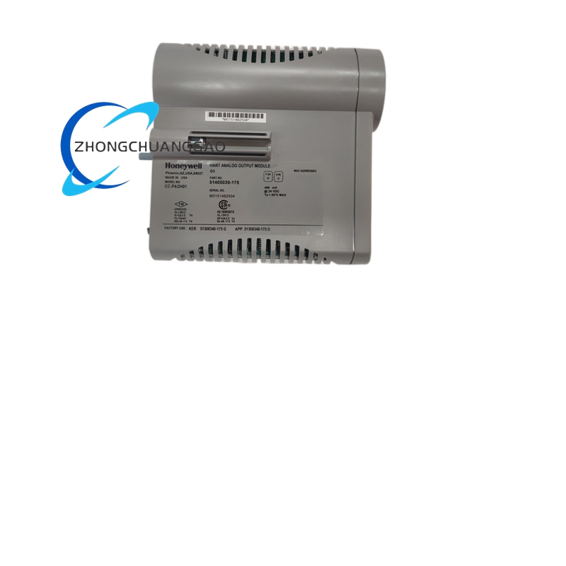
- Single-width rack module dimensions: 22.5mm (W) × 130mm (H) × 135mm (D)
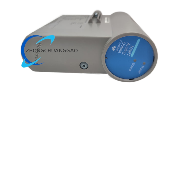
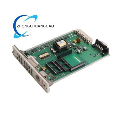
- Front panel equipped with 8 channel status LED indicators, power supply LED, module fault diagnostic LED
- Rear gold-plated edge connector for C200 backplane digital communication bus interface
- Removable screw-type terminal block with dedicated output signal pairs and shielding ground terminals
- Mechanical locking latch with anti-vibration spring to fix module securely inside rack slots
Working Principle
C200 main controller transmits digital control setpoint values via backplane bus to CC-PAOH01 on-board microprocessor. Microprocessor retrieves stored channel configuration parameters (signal range, ramp rate, fail-safe state), executes digital ramp limiting calculation to avoid abrupt output changes, then sends digital values to independent 16-bit D/A converters for each channel. Converted analog signals pass through isolated high-current drive circuits with short-circuit protection before transmitting to field actuators via front terminal block. Real-time output loop current monitoring circuits detect short-circuit conditions; upon fault detection, channel drive circuit immediately cuts off output and uploads fault diagnostic code to controller and Experion PKS HMI. When controller power loss occurs, on-board logic executes pre-configured fail-safe output state automatically.
Advantage Highlights
- Ultra-high 750Ω maximum loop load resistance supports extremely long wiring distances to remote control valves
- Independent short-circuit protection per channel prevents single channel fault from disabling entire module operation
- Adjustable output ramp rate eliminates process shock caused by fast actuator position changes, stabilizing continuous production
- Customizable per-channel fail-safe modes meet safety shutdown logic requirements for hazardous process loops
- 2500VAC full channel isolation eliminates ground loop noise distortion of analog control signals
- ATEX certified for Division 2 hazardous industrial zone installation
- Hot swap maintenance capability avoids full production shutdown during module replacement in redundant control systems
Applicable Industries
Petroleum refining, chemical process manufacturing, thermal power generation, natural gas processing, pulp & paper continuous production, pharmaceutical batch control, water treatment flow regulation systems
Installation Requirements
- Install only within official Honeywell C200 series control rack and matching backplane chassis
- Maintain minimum 15mm vertical air gap between adjacent modules for forced air cooling circulation
- Cabinet cooling airflow minimum standard: 0.7 m³/min per rack assembly
- Analog output wiring uses shielded twisted pair cable, cable shield single-point grounded at cabinet earth bar
- Terminal block allowable maximum wire gauge: 14 AWG solid copper conductor
- Rack installation location continuous vibration amplitude less than 0.5mm
- Separate analog output control wiring from high voltage AC power and motor drive cables with minimum 30cm clearance distance
Operation & Maintenance Precautions
- Do not short-circuit output channel terminals during live operation; repeated short-circuit events degrade internal drive circuit lifespan
- Terminal block screw tightening torque fixed at 0.8 N·m to avoid loose connection voltage drop and actuator position drift
- Verify all field actuator load resistance values do not exceed module maximum 750Ω limit before commissioning
- Anti-static wrist strap mandatory during module disassembly, wiring modification and replacement work
- Front panel cleaning only permitted with dry anti-static microfiber cloth; liquid chemical cleaners prohibited
- Confirm redundant standby controller fully active before performing hot swap module maintenance
- Spare modules must store in sealed anti-static packaging with desiccant packs, maintain storage humidity below 80%



























-430x430.jpg)
-430x430.jpg)
-430x430.jpg)
-430x430.jpg)

Reviews
There are no reviews yet.