2. Product Brief Introduction
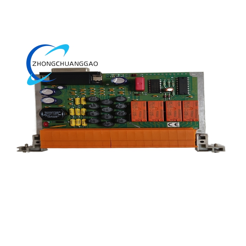
This module is a dedicated relay expansion accessory card customized exclusively for Honeywell System57 gas detection control rack and matches all System57 single-channel gas detection main control cards including 05701 series signal conditioning boards. It receives digital alarm logic commands transmitted from rack backplane bus after gas concentration threshold judgment by host detection card, drives four independent built-in electromagnetic SPDT relay channels to realize passive switching output for external on-site equipment. It executes gas pre-alarm, high-concentration alarm, equipment fault alarm three kinds of contact switching control for external audible alarms, indicator beacons, solenoid valves and auxiliary starter equipment. All channel relay action parameters are configured uniformly through System57 rack central engineering configuration card without onsite hardware jumper modification. The card adopts unified System57 backplane communication protocol, completes real-time relay working status feedback to rack main bus and system upper DCS host, and supports cascaded connection with 05704 series multi-relay expansion cards for further output channel expansion.
3. Technical Specifications
- Rated Working Input Power Supply: 24VDC nominal supply voltage, allowable continuous input range 18VDC ~ 32VDC, full-circuit built-in reverse polarity protection circuit
- Internal Relay Configuration: 4 channels independent SPDT (Single Pole Double Throw) electromagnetic relay per single card, each relay owns isolated common, normally open and normally closed contact terminals
- Single Relay Contact Rated Load Capacity: 5A @240VAC resistive load; 5A @30VDC DC load for each contact group
- Standard Outer Dimension (3U Eurocard Specification): Height 132.5mm × Width 25.4mm × Depth 119mm
- Module Static Power Consumption: Typical operating power 3.5W; maximum full-load rated power 6.5W
- Allowable Wiring Specification for Field Terminals: Supports maximum cross-section 2.5mm² (14AWG) copper insulated control wire access
- Dielectric Withstand Voltage Rating: 500VAC/60s isolation between internal control logic circuit and external relay contact terminal circuit without breakdown or over leakage current
- Continuous Operating Ambient Temperature Range: -20℃ ~ +60℃; long-term sealed storage temperature: -40℃ ~ +85℃
- Rated Working Relative Humidity Scope: 5%~95% non-condensing relative humidity under full operating temperature range
- Formal Certified Standard: CE industrial safety certification, UL508 industrial control component certification, ATEX secondary control equipment conformity certification
- Backplane Bus Definition: System57 proprietary parallel digital backplane bus with 56-pin gold finger interface matching standard System57 rack slot definition
4. Functional Features
- Four fully electrically isolated SPDT relay channels, each channel independently configurable to bind pre-alarm, high gas alarm or detector fault alarm logic via system configuration without hardware component replacement.
- Built-in terminal surge suppression diode on every external relay wiring port to absorb inductive spike generated by external valve coil and alarm equipment power switching action.
- Front panel embedded four independent LED running indicators corresponding to each relay channel, LED lights synchronously once respective relay coil is energized and contact switches.
- Real-time relay status detection circuit integrated inside PCB; contact open/closed abnormal state is uploaded to System57 rack backplane bus for system fault recording and remote upper computer monitoring.
- Standard plug-in 3U card structure, directly inserted into System57 19-inch standard rack card guide without additional DIN rail fixing accessory.
- Unified front panel concentrated terminal layout classified by NO/NC/COM contact definition to avoid cross wiring confusion during field wiring construction.
- Supports cascaded expansion with 05704-A series multi-relay expansion daughter cards to expand total system relay output quantity flexibly according to on-site project demand.
- Built-in hardware anti-jamming filter circuit for backplane input control signal to restrain cabinet internal power frequency interference avoiding false relay switching action.
5. Performance Parameters
- Relay single channel pull-in response switching time: ≤8ms from receiving backplane trigger signal to mechanical contact complete closing action
- Single relay mechanical service lifespan: ≥10,000,000 times no-load switching cycles under rated ambient working environment
- Contact electrical service lifespan under full rated load: ≥100,000 times continuous rated load switching operations
- Full module MTBF value under standard industrial rated working condition: 208000 continuous running hours
- Backplane signal state refresh cycle: Fixed 10Hz cyclic status upload of four-channel relay working data to System57 rack main bus
- Internal circuit temperature drift coefficient within rated operating range: ≤15ppm/℃ full circuit power parameter variation
- Terminal screw wiring fastening cycle life: ≥1800 times repeated wire tightening and loosening operation without terminal thread sliding damage
6. Material Composition
- Main Core PCB Substrate: FR-4 high Tg flame retardant glass fiber circuit board with full immersion tin anti-oxidation surface treatment, SMT+through-hole mixed component layout technology.
- Front Panel Outer Frame: Black matte electrostatic coated cold rolled steel sheet with surface anti-rust passivation treatment, UL94-V0 flame retardant plastic embedded indicator window structure.
- External Wiring Terminal Block Base: PA66 UL94-V0 fire-resistant insulation engineering plastic; conductive insert adopts solid nickel-plated brass material, locking screw is zinc alloy anti-loose component.
- Internal Electromagnetic Relay Core: High temperature resistant bakelite framework plus silver alloy contact piece, copper enameled wire relay coil assembly.
- Backplane Gold Finger Connector: Copper substrate electroplated with 1.2μm hard gold layer for long-term repeated plug abrasion resistance.
- Onboard Passive Electronic Components: Automotive-grade TVS surge suppression diodes, X7R high stability multilayer ceramic capacitors, metal film precision fixed resistors.
- Internal Fixed Support Components: High temperature modified PA66 plastic positioning pillars for anti-vibration fixation between PCB and front metal panel.
7. Structural Characteristics
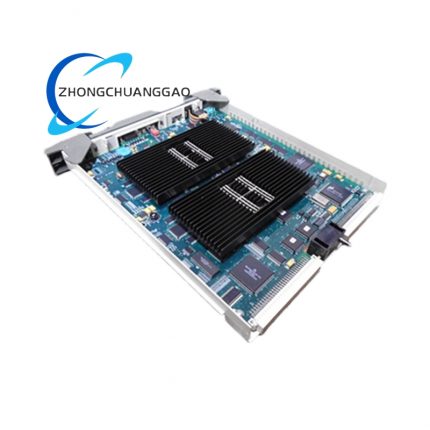
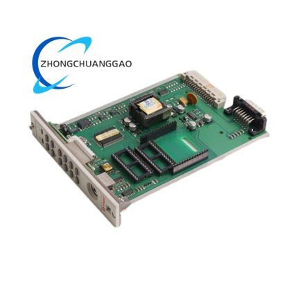
- Split integrated structure consisting of front metal fixed panel + rear PCB core assembly, follows standard single-width 3U Eurocard dimensional specification matching all System57 original rack card slots.
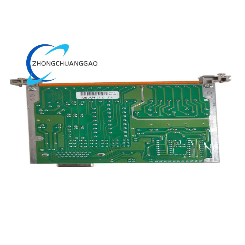
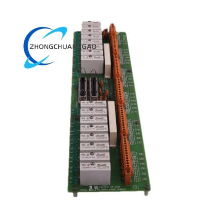
- Internal PCB functional zoning layout: Backplane gold finger and power supply circuit concentrated at rear end, relay coil driving logic circuit arranged in middle zone, four groups of relay components and external wiring terminals fixed near front panel side.
- Four independent relay cavities separated by internal plastic isolation ribs to block electromagnetic crosstalk between adjacent relay channels during pull-in action.
- Front panel pre-drilled two sets of upper/lower fixing screw holes for locking module with rack frame to eliminate mechanical clearance caused by equipment runtime vibration.
- Permanent high-temperature resistant ink silkscreen marking on front panel: terminal definition, channel serial number, part number and corresponding LED function identification with anti-solvent corrosion property.
- Terminal area partition layout by four independent channel groups; each channel COM, NO, NC terminals centralized arranged in fixed area to realize classified field wiring management.
8. Working Principle
Step 1: Digital Alarm Command Receiving
System57 host gas detection control card completes gas concentration calculation and threshold comparison, converts trigger instruction into digital logic signal and transmits to 05704-A-0121 via rack internal backplane bus.
Step 2: Internal Logic Conversion & Coil Drive
Onboard control circuit receives digital trigger signal, filters out interference noise and outputs stable driving voltage to corresponding channel relay coil to generate electromagnetic pull-in force.
Step3: Mechanical Contact Switching Action
Energized relay coil drives internal mechanical armature action; normally open (NO) contact closes and normally closed (NC) contact opens to change external field equipment loop conduction state.
Step4: External Field Equipment Control
External alarm horn, warning beacon, cut-off solenoid valve and auxiliary control equipment access relay contact terminals via field cable; contact status change realizes equipment startup/shutdown on-site.
Step5: Working Status Feedback Collection
Built-in contact detection circuit collects real-time relay closing/opening state, packages status data into digital bus signal and reversely uploads to System57 rack backplane for centralized system recording and remote DCS display.
9. Advantage Highlights
- Full factory pre-assembled and pre-tested finished card; direct plug-and-play replacement without onsite circuit debugging or parameter modification to shorten gas detection system maintenance downtime.
- Four-channel fully isolated SPDT contact design supports flexible selection of normally open or normally closed wiring mode adapting diversified field equipment control requirement.
- Wide 18~32VDC input power range adapts industrial site UPS power supply voltage fluctuation during grid power failure switching condition.
- Standard unified 3U Eurocard size realizes seamless compatible installation with all original Honeywell System57 series racks without cabinet space reconstruction modification.
- Independent per-channel surge protection structure effectively avoids relay component burnout caused by external inductive load reverse electromotive force impact.
- Unified terminal specification unifies field wiring standard, reduces wrong wiring probability during site construction and later routine equipment overhaul work.
- Compatible with all mainstream 05701 series single-channel gas detection control cards covering catalytic, electrochemical and infrared sensor matching control modules.
10. Applicable Industries
- Petrochemical Industry: Refinery, chemical synthesis workshop, hazardous chemical storage tank area gas detection cabinet alarm output expansion
- Natural Gas & LNG Industry: City gas gate station, LNG storage depot, long-distance gas pipeline valve chamber gas leakage alarm control
- Thermal Power Generation Industry: Coal stockyard, hydrogen production room, transformer chamber combustible/toxic gas monitoring system external equipment driving
- Pharmaceutical Fine Chemical Industry: API synthesis workshop organic solvent vapor concentration monitoring alarm interlock control
- Offshore Oil & Gas Industry: Offshore production platform module, FPSO cabin fixed gas detection system peripheral equipment control
- Waste Environmental Treatment Industry: Municipal landfill, hazardous waste incineration plant harmful gas concentration interlock cut-off control
- Marine Vessel Industry: Ship engine room, cargo hold fixed gas and flame detection cabinet alarm output expansion
11. Model Series Affiliation
- Parent Product Series: Honeywell System57 / 05704 Series Relay Expansion Card Family for Gas Detection Rack System
- Same-series sibling standard model list:
- 05704-A-0144: 12-channel multi-relay expansion daughter card for cascaded channel quantity expansion
- 05704-A-0145: Low-power DC dedicated four-channel relay card for intrinsically safe hazardous area application
- Compatible matching host equipment: Full range Honeywell System57 19-inch standard master rack, all 05701-A series single-channel gas detection signal conditioning cards, System57 rack engineering configuration card, upper DCS/PLC monitoring host
12. Installation Requirements
- Installation Environment Rule: Must be mounted inside closed ventilated industrial control cabinet; installation inside high-humidity, corrosive gas accumulation and explosive classified hazardous cabinet compartment is prohibited.
- Rack Plug-in Specification: Insert module along System57 dedicated rack internal plastic card guide track until rear gold finger fully engages backplane socket; fasten front panel upper and lower fixing screws with rack frame to eliminate vibration gap.
- Field Wiring Specification: External relay load cable uses 1.0~2.5mm² copper insulated control wire; all field cable shielding layer single-point concentrated connected to cabinet independent PE protective earth terminal, separated from high voltage power distribution grounding loop.
- Heat Dissipation Clearance Requirement: Minimum 10mm vacant space reserved above and below module inside rack for natural convection heat dissipation; no high-power heating components installed within 20mm surrounding space of module housing.
- Pre-installation Confirmation: Confirm corresponding alarm logic binding parameter on System57 engineering card before rack insertion installation to match field actual equipment control requirement.
- Cabinet Grounding Standard: Module reserved public grounding terminal connects to cabinet independent PE grounding bus via dedicated grounding copper wire.
13. Use & Maintenance Precautions
- Strictly forbid hot plugging/unplugging module under rack powered running state; live plug action generates instantaneous surge voltage leading to permanent damage of onboard drive circuit and relay components.
- Never access AC/DC load exceeding rated contact specification into any relay COM/NO/NC terminals; over-range load directly causes relay contact ablation and channel permanent failure.
- All field wiring disassembly and modification operation must be executed after cutting off rack total 24VDC control power supply to avoid accidental short-circuit triggering full gas detection system fault interlock shutdown.
- Quarterly regular maintenance only uses dry lint-free cloth to wipe front panel and terminal dust; organic solvent, alcohol and liquid cleaning agent direct contact with PCB and plastic terminal base is forbidden.
- Unused spare modules must be sealed inside anti-static shielding bag and stored under 10℃~35℃ dry constant temperature environment; open-air damp and high-temperature long-term storage is prohibited.
- On-site fault replacement only permits original Honeywell factory certified genuine 05704-A-0121 module; third-party refurbished or imitation substitute modules cannot access formal certified System57 gas detection control system.
- Avoid high-frequency inverter, arc welding and high-power RF equipment installed within 35cm distance of module installed control cabinet to prevent strong electromagnetic radiation inducing false relay mis-switching action.


























-430x430.jpg)
-430x430.jpg)

Reviews
There are no reviews yet.