Key Technical Specifications:
-
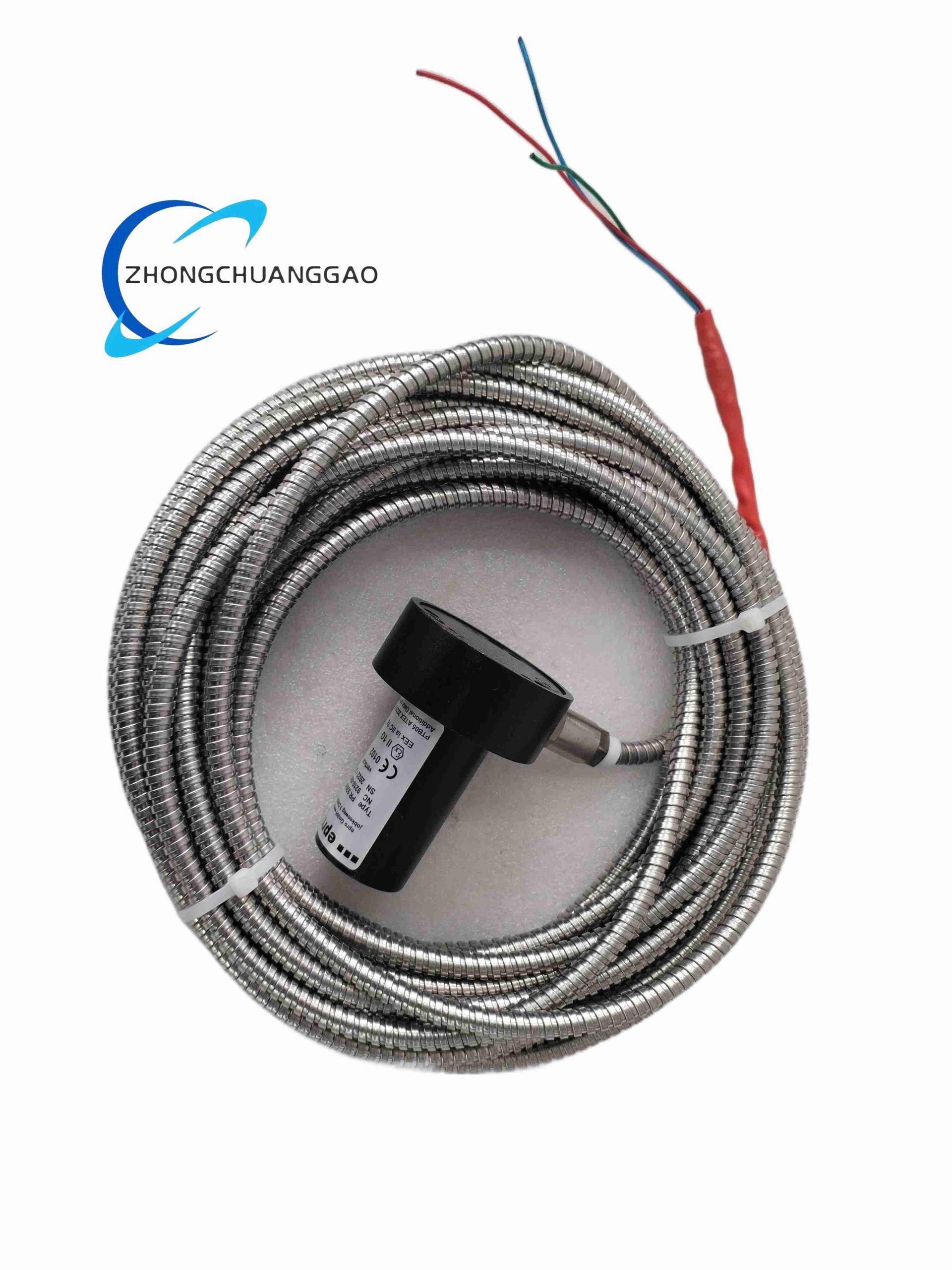
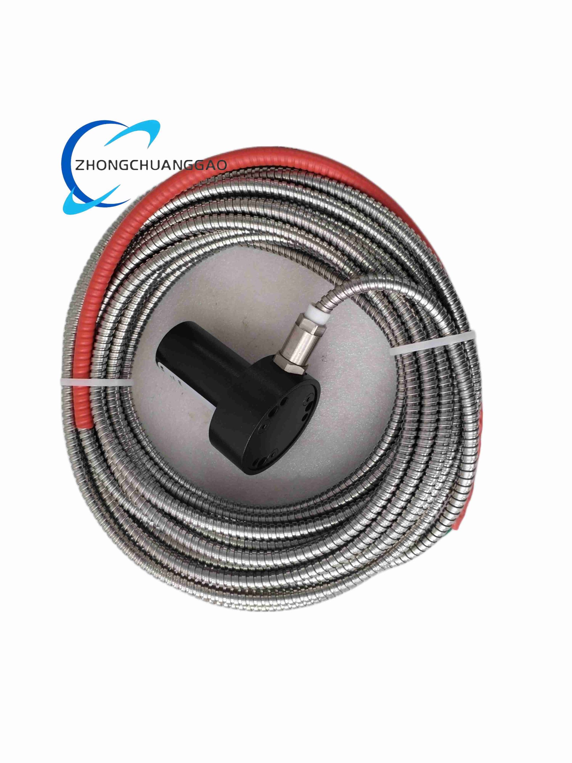
Sensor Type: Electrodynamic (moving coil / spring-mass system), self-generating — no external power required
-
Mounting Orientation: Vertical ±30° (model /203 = vertical)
-
Sensitivity: 28.5 mV/mm/s (723.9 mV/in/s) ±5% @ 80 Hz, 20°C, 100 kΩ load
-
Frequency Response: 4 Hz – 1000 Hz (±3 dB)
-
Natural Frequency: 4.5 Hz ± 0.75 Hz @ 20°C
-
Measuring Range: ±1500 µm (peak), mechanical limit 3000 µm pk-pk
-
Amplitude Linearity: <2%
-
Transverse Sensitivity: ≤0.13 @ 110 Hz
-
Max Continuous Acceleration: 10 g; intermittent 20 g
-
Coil Resistance: 1875 Ω ±10%
-
Coil Inductance: ≤90 mH
-
Output Signal: Low-impedance AC voltage proportional to velocity
-
Operating Temperature: -20°C to +100°C
-
Humidity: 0–100% RH (non-condensing)
-
Housing Material: Aluminum alloy (Al Mg Si Pb F28) or stainless steel — sealed
-
Connection: Integral shielded PTFE cable (typical 3 m / 5 m armored) or MIL-C-5015/ Harting plug option
-
Protection Class: IP65 / IP67 (depending on cable variant)
-
Weight: approx. 0.93 kg
-
Certifications: CE, ATEX / IECEx optional for hazardous area versions
Applications: Steam / gas / hydro turbine bearing housing vibration, large compressor & fan casing vibration, gearbox housing monitoring, power plant & petrochemical rotating equipment predictive maintenance.
Installation & Notes: Bolt to machine casing via M8×1.25 stud. Do NOT use in strong DC magnetic fields. Keep cable away from power cables to avoid EMI. Sensor orientation affects gravity-induced DC offset — vertical models must be mounted within specified tilt tolerance.
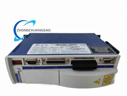
2. Kollmorgen PRD-B040EAIZ-33 — AKD Series Servo Drive
Product Name: Kollmorgen AKD PRD-B040EAIZ-33 Digital Servo Drive
Product Brief: High-performance PWM servo amplifier from the AKD platform. Provides torque, speed, and position control for AKM-series permanent magnet synchronous motors. Supports EtherCAT (EAIZ = EtherCAT, no safe torque off in base code, I/O config variant) and advanced auto-tuning.
Key Technical Specifications:
-
Drive Family: Kollmorgen AKD — model PRD-B040 → 40 A continuous current (~33 kW peak power capability depending on bus voltage)
-
Input Power: 3 × 208–480 VAC (+10%/-15%), 50/60 Hz; DC bus internally regulated
-
Continuous Output Current: 40 A rms (depends on exact sub-suffix; typical for B040 frame)
-
Peak Output Current: approx. 80 A (limited by drive rating and motor inductance)
-
Control Modes: Torque (Current), Velocity, Position (Indexing), Electronic Gearing, Camming
-
Feedback Supported: Resolver, EnDat 2.1/2.2, Hiperface DSL, BiSS-C, incremental encoder
-
Communication / Fieldbus: EtherCAT (CoE — CANopen over EtherCAT), also supports Modbus TCP on some variants
-
Safe Motion: STO (Safe Torque Off) SIL 3 / PL e available (verify sub-suffix for inclusion)
-
Bandwidth — Current Loop: >3 kHz; Velocity & Position loops fully digital with auto-notch filtering
-
Regenerative Braking: Built-in regenerative energy management; external brake resistor terminal provided
-
Digital I/O: Configurable general-purpose inputs/outputs, home/limit switch, fault relays
-
Indicators: Multiline alphanumeric display + status LEDs
-
Cooling: Forced-air (internal fan)
-
Ambient Temperature: 0°C to +40/45°C (derating above); storage -25°C to +70°C
-
Certifications: CE, UL, cUL, TÜV SIL 3 (with STO)
Features: Plug-and-play motor recognition (AKM motor auto-ID), graphical tuning software (WorkBench), feed-forward & jerk-limited motion profiles, multi-axis synchronization via distributed clocks (EtherCAT).
Applications: CNC machine tools, semiconductor assembly, packaging machinery, robotic joints, printing presses, high-speed pick-and-place.
Installation & Notes: Requires proper grounding and shielded motor/feedback cables. Size according to continuous RMS current — not just peak. Use external braking resistor if frequent deceleration from high inertia. Commission via Kollmorgen WorkBench before first run.
3. Martek PS2494-YE — High-Voltage Input DC Power Supply (Ionpure / Electrodeionization)
Product Name: Martek Power PS2494-YE AC-DC Switching Power Supply Unit (for Ionpure EDI stacks)
Product Brief: Industrial high-voltage DC output switching power supply designed to drive electrodeionization (EDI) modules or similar high-voltage/low-current DC loads. Accepts wide-range 3-phase AC input.
Key Technical Specifications:
-
Input Voltage: 220–660 VAC, 3-phase, 50/60 Hz, approx. 16 A max input current
-
Output Voltage: Adjustable 30–600 VDC
-
Output Current: Up to 13.2 A (continuous)
-
Rated Power: approx. 8 kW (600 V × 13.2 A)
-
Topology: Switch-mode PWM with active PFC
-
Voltage / Current Regulation: ±1% typical line/load regulation
-
Protections: Overvoltage lockout (OVP), overload (hiccup mode auto-recovery), short-circuit, over-temperature
-
Cooling: Forced air (internal fan)
-
Indicators: Power-on LED, fault LED, voltage/current meters on front panel (variant dependent)
-
Mounting: Panel / rack mount (typically 19″ subrack or cabinet-mounted)
-
Operating Temp: 0°C to +50°C (derate above 40–50°C depending on revision)
-
Compliance: UL / CE / RoHS (typical for Martek Power industrial units)
Applications: Powering Ionpure® continuous electrodeionization (CEDI) stacks in ultrapure water systems, electro-coagulation, electrophoresis, laboratory HV DC source.
Installation & Notes: Verify input wiring is correct 3-phase before energizing — wrong phasing will not damage but may cause alarm. Output is ungrounded HVDC — observe creepage & clearance. Use external fusing on AC input side. Adjust voltage/current via front panel potentiometers or remote analog signals (check revision for analog prog. capability).
4. HIMA PS1000 230 010 (PS100023001) — Safety-Related System Power Supply Module
Product Name: HIMA PS1000/230 — 24 VDC System Power Supply Module for HIMax / HIQuad Safety Systems
Product Brief: Galvanically isolated, fanless switched-mode power supply engineered for SIL 3 safety-related control systems. Converts 230 VAC mains to regulated 24 VDC to power HIMA safety CPUs, I/O racks, and communication modules. Supports parallel redundant (1+1 / N+1) configuration.
Key Technical Specifications:
-
Ordering / Part No. Reference: PS1000/230 010 → commonly referenced as PS100023001 or 982200080
-
Input Voltage: 190–264 VAC (nominal 230 VAC), 48–62 Hz; some variants support 115/230 VAC selectable
-
Output Voltage: 24 VDC nominal (adjustable ±5%)
-
Rated Output Current: 10 A continuous @ 40°C ambient (some frame versions rated 40 A — confirm exact subrack config; standard PS1000/230 = 10 A)
-
Output Power: 240 W (10 A version)
-
Efficiency: >85% @ full load
-
Safety Integrity: Designed to IEC 61508SIL 3 requirements; galvanic isolation input/output >3 kV
-
Redundancy: Supports parallel operation with diode OR-ing in HIMA M 3421 subrack for 1+1 redundancy
-
Protections: Overvoltage limitation (<30 VDC even on fault), short-circuit proof, overtemperature protection with auto-recovery
-
Diagnostics: Front-panel LEDs — “Power OK” (green), “Error” (red); optionally monitored via system backplane
-
Cooling: Convection (no fan)
-
Mounting: Plug-in cassette for HIMA 19″ subrack M 3421 or DIN rail adapter
-
Operating Temp: 0°C to +60°C
-
MTBF: >200,000 h (Telcordia / MIL-HDBK method)
Applications: Emergency Shutdown (ESD) system power, Fire & Gas system power, Burner Management System (BMS) power, Safety Instrumented Function (SIF) loop power in oil & gas, refinery, chemical plants.
Installation & Notes: Insert fully into coded backplane — mismatched coding prevents insertion. Ensure minimum 100 mm top/bottom clearance for convection cooling. For redundancy, install two modules in adjacent slots with OR-ing diodes — no external OR-ing required if using HIMA subrack. Verify earth continuity before commissioning.
5. VanGuard PSMU-350-3 — CompactPCI 350W Power Supply Module
Product Name: Vanguard PSMU-350-3 CompactPCI (cPCI) 350W System Power Module
Product Brief: 3U/6U CompactPCI standard-compliant DC power supply delivering +3.3 V, +5 V, +12 V, -12 V from universal AC input. Intended for CPCI embedded computing, telecom, and test systems requiring hot-swap capable, redundant-ready power.
Key Technical Specifications:
-
Model: PSMU-350-3 (also referenced as CPCI-350Q-P-38 variant)
-
Input Voltage: 85–264 VAC, 47–63 Hz (universal); optional 12–36 VDC on some builds
-
Output Rails & Currents (typical):
-
+3.3 VDC @ 60 A max
-
+5 VDC @ 50 A max
-
+12 VDC @ 15 A max
-
-12 VDC @ 2 A max
-
+5 VSB (standby) @ 3 A
-
Total Output Power: 350 W continuous (380 W peak for 10 s)
-
Efficiency: ≥82% @ full load, typically 85%
-
Load / Line Regulation: ±0.5% line, ±1% load
-
Isolation Voltage: 3000 VAC input-output (1 min), 500 VAC output-output
-
Protections: OVP, OCP (independent per rail), OTP, auto-recovering SCP
-
Hot-Swap: PICMG 2.11 compliant hot-swap with inrush limiting & backplane sequencing
-
Remote Management: Optional PMBus monitoring (voltage, current, temp, fault status)
-
Redundancy: Supports N+1 parallel for no-break operation
-
Indicators: PWR (green), RED (yellow — redundancy status), ERR (red), per-rail green LEDs
-
Cooling: Passive heatsink (fanless) — requires chassis airflow
-
Operating Temp: -40°C to +70°C (no derating startup from -40°C; consult load curve)
-
MTBF: ≥800,000 h (MIL-HDBK-217F, 25°C)
-
Compliance: UL 60950-1, CE, CB, RoHS; EMC per EN 55022Class B
-
Mechanical: 6U × 8HP (approx. 261.6 × 160 × 40.4 mm) CPCI form factor; 64-pin power connector per IEC 61076-4-101
Applications: CPCI-based data acquisition chassis, military/aerospace rugged embedded computers, telecom node equipment, industrial test & measurement PXI/cPCI systems.
Installation & Notes: Insert into CPCI backplane — ensure chassis provides adequate forced airflow over supply heatsink area. For redundant config, populate adjacent slot and enable load sharing via OR-ing. Do not exceed total 350 W combined rail loading. Verify +5 VSB presence before system boot if used for wake-on-LAN / remote management.
6. Microelettrica Scientifica PTC1177 — PTC Positive Temperature Coefficient Starting Relay (for Compressors)
Product Name: Microelettrica Scientifica (now often referenced as Tecumseh / generic OEM) PTC1177 Start Relay for Single-Phase Induction Motor / Hermetic Compressor
Product Brief: Ceramic PTC (Positive Temperature Coefficient thermistor) start relay used to momentarily engage the start winding of single-phase capacitor-start or split-phase compressor motors. When energized, the PTC heats up and becomes high-resistance, effectively removing the start winding from circuit after run-up.
Key Technical Specifications:
-
Device Type: PTC Start Relay (Semiconductor ceramic pellet type)
-
Typical Use: Refrigeration / air-conditioning hermetic compressors (e.g. Tecumseh, Embraco, Danfoss small frames)
-
Rated Voltage: 110–250 VAC (line voltage applied across PTC during start cycle)
-
Switch-off Resistance (Hot): >10–30 kΩ (typical for start-relay PTC — blocks current after heating)
-
Cold (Room Temp) Resistance: 15–50 Ω (allows start winding current to flow at switch-on)
-
Trip / Switch Time: 0.1–0.5 s (depends on motor inrush & PTC characteristics)
-
Max Switching Current: Typically 15–30 A inrush (verify per compressor HP)
-
Insulation Resistance: ≥100 MΩ @ 100 VDC
-
Dielectric Strength: 1500–2000 VAC (terminal to case, 1 min)
-
Operating Temp Range: -30°C to +85°C (ambient); PTC pellet reaches 120–150°C internally during operation
-
Terminals: Quick-connect spade terminals (typically 1/4″ or 3/16″)
-
Mounting: Clip-on or socket mount onto compressor terminal box
Features & Working Principle: Uses barium titanate ceramic PTC whose resistance rises sharply above Curie temperature. On compressor start, cool PTC conducts → start winding energized. After ~100–300 ms, self-heating raises PTC above Curie point → high resistance → start winding effectively disconnected. No mechanical contacts = silent operation & long life.
Applications: Domestic / commercial refrigerator compressors, freezer compressors, small air-conditioner condensing units, vending machine refrigeration.
Installation & Notes: Must be matched to compressor HP & start winding impedance — incorrect PTC causes failure to start or overheating. Ensure good thermal contact is NOT required (PTC self-heats). Allow cool-down time (~3 min) before re-start to permit PTC to return to low-resistance state. Replace together with start capacitor if applicable.
7. ProSoft PTQ-PDPMV1 — PROFIBUS DP-V1 Master Module for Schneider Quantum
Product Name: ProSoft Technology PTQ-PDPMV1 PROFIBUS DP-V1 Master Communication Module for Schneider Electric Quantum PLC
Product Brief: Single-slot Quantum backplane module that turns a Schneider Quantum PLC into a PROFIBUS DP-V1 Class 1 Master. Enables cyclic I/O exchange and acyclic services (alarms, parameterization, diagnostics) with up to 125 PROFIBUS slave devices.
Key Technical Specifications:
-
Platform Compatibility: Schneider Electric Quantum series (140CPUxxxx) with Unity Pro / Concept
-
Protocol: PROFIBUS DP-V0 + DP-V1 (Master, Class 1 & Class 2 services)
-
Communication Port: 1 × 9-pin D-sub female (RS-485), optically isolated
-
Baud Rate: 9.6 kbps to 12 Mbps (auto-baud detection supported)
-
Max Slaves: 125 (31 per segment without repeater; add repeaters for more)
-
Cyclic Data Capacity: Up to 1536 bytes Input + 1536 bytes Output (per master — depends on PLC memory mapping)
-
Backplane Current Draw: max 1100 mA @ 5 VDC
-
Configuration: ProSoft Configuration Builder (PCB) software; also FDT/DTM via ComDTM for offline/on-line configuration
-
Hot Standby Support: Compatible with Quantum Hot Standby (HEC) — max 4 PTQ modules per rack in HS config
-
Processor: Infineon C165 microcontroller + Siemens ASPC2 Step E ASIC
-
Status Indicators: Module STAT, Backplane COM, Master RUN, Net Diag, Token LEDs
-
Mechanical: Standard Quantum single-width module (approx. 250 × 103.9 × 40.3 mm)
-
Operating Temp: 0°C to +60°C
-
Humidity: 5–95% RH non-condensing
-
Vibration/Shock: IEC 60068-2-6(3 g, 10–150 Hz), IEC 60068-2-27(30 g, 11 ms)
-
Certifications: CE, UL, CSA, PROFIBUS PTO certified, ATEX Zone 2 (some revisions)
Features: Extended DP-V1 diagnostics (read slave diagnostic alarms), online slave parameter write/read, supports multiple masters in one Quantum rack, built-in web server on some firmware versions for basic diagnostics.
Applications: Integrating legacy or third-party PROFIBUS DP field devices (drives, valves, remote I/O, analyzers) into Schneider Electric Quantum process control or SCADA systems; retrofit of S5-interface machinery into modern DCS/PLC architecture.
Installation & Notes: Install in any available slot except slot 1 (reserved for CPU in most Quantum racks). Terminate PROFIBUS network both ends with 220 Ω resistors. Use screened twisted pair (PROFIBUS cable type A). Ensure GSD file from ProSoft is imported into configuration tool. Set correct station address via DIP switches or software before inserting into live rack.
8. National Instruments PXIe-8135 — PXI Express Embedded Controller (Intel Core i7)
Product Name: NI PXIe-8135 PXI Express Embedded Controller (Intel Core i7-3610QE, quad-core)
Product Brief: High-performance embedded controller for PXI Express chassis. Features 3rd-gen Intel Core i7 quad-core processor, removable storage option, integrated peripherals, and up to 8 GB/s system bandwidth to PXIe backplane. Runs Windows or NI Linux Real-Time.
Key Technical Specifications:
-
Processor: Intel Core i7-3610QE — 4 cores / 8 threads, 2.3 GHz base, up to 3.3 GHz Turbo Boost (single core)
-
Chipset: Mobile Intel QM77 Express
-
Memory (Standard / Max): 4 GB DDR3-1600 SO-DIMM standard (1 slot), expandable to 8 GB or 16 GB depending on revision
-
Storage: 2.5″ SATA HDD/SSD standard; optional front-accessible removable drive caddy (for declassification / image swap)
-
PXI Express Bandwidth: Up to 8 GB/s system bandwidth, 4 GB/s per-slot (x4 Gen 2 PCIe to backplane)
-
Front Panel I/O:
-
2 × USB 3.0 SuperSpeed
-
4 × USB 2.0 High Speed
-
2 × Gigabit Ethernet (10/100/1000BASE-TX)
-
1 × RS-232 serial port (D-sub 9)
-
DisplayPort (some revisions also have DVI-I via adapter)
-
Power & HDD activity LEDs
-
Watchdog Timer: Hardware watchdog with system reset or NMI on timeout
-
Operating Systems Supported: Windows 7/10 (64-bit), NI Linux Real-Time (PharLap ETS deprecated on newer; Linux RT supported), LabVIEW Real-Time
-
Slot Requirement: Occupies Slot 1 of PXIe chassis (3U single-slot)
-
Power: Supplied by PXI chassis backplane (typical 50–80 W depending on config)
-
Operating Temp: 0°C to +50°C (typical for lab grade; extended-temp versions may differ)
-
Dimensions: 160.7 × 33.3 × 269.5 mm (3U PXIe module form factor)
Applications: Automated test systems (ATE), RF / mixed-signal measurement, hardware-in-the-loop (HIL) simulation, data acquisition with intensive signal processing, production test stands.
Installation & Notes: Insert into Slot 1 of PXIe chassis — do NOT mix with older PXI-only controllers in same chassis. Use NI-MAX to identify and configure. For RT targets, format and install LabVIEW Real-Time via NI Measurement & Automation Explorer. Ensure chassis cooling is adequate — i7 controller dissipates significant heat.
9. National Instruments PXIe-8840 — PXI Express Embedded Controller (Intel Core i5/i7 Options)
Product Name: NI PXIe-8840 PXI Express Embedded Controller (Intel Core i5-4400E or Core i7-5700EQ options)
Product Brief: General-purpose embedded controller for PXI Express systems. Offers dual-core i5 or quad-core i7 options, USB 3.0, Gigabit Ethernet, and supports Windows / NI Linux Real-Time. Designed for test, measurement, and DAQ applications requiring moderate to high CPU throughput.
Key Technical Specifications:
-
Processor Options:
-
Dual-Core: Intel Core i5-4400E — 2.7 GHz base, 3.3 GHz Turbo, 2 cores / 4 threads
-
Quad-Core: Intel Core i7-5700EQ — 2.6 GHz base, 3.2 GHz Turbo, 4 cores / 8 threads
-
Memory: 2 GB or 8 GB DDR3L-1600 SO-DIMM (1 slot, expandable to 16 GB on some configs)
-
Storage: 250 GB or 320 GB 2.5″ SATA HDD (SSD upgrade available); some versions support mSATA
-
PXIe Bandwidth: x4 PCIe Gen 2 to backplane — up to 3.2 GB/s system bandwidth
-
Front Panel I/O:
-
Watchdog Timer: Yes — configurable timeout & action
-
OS Support: Windows 7/10 (64-bit), NI Linux Real-Time, Legacy PharLap ETS (check part number suffix)
-
Slot: PXIe Slot 1 (3U single-width)
-
Operating Temp: 0°C to +55°C
-
Power: Via PXI chassis backplane
Feature Differences vs PXIe-8135: PXIe-8840 is typically a later-generation controller (Haswell/Broadwell vs Ivy Bridge) with improved graphics integration and USB 3.0 native; PXIe-8135 (i7-3610QE) is older but still quad-core — performance comparable in many DAQ tasks; choose based on OS compatibility & chassis slot availability.
Applications: Production test, validation labs, mixed-signal data acquisition, university research labs, portable PXI test carts.
Installation & Notes: Same as PXIe-8135 — install in Slot 1. Use NI MAX for identification. For Linux RT targets ensure correct kernel/RT image version matches controller generation. Ground chassis properly to minimize EMI on sensitive analog measurements.
10. Honeywell R7247C1001 — UV Flame Amplifier (Dynamic Self-Check)
Product Name: Honeywell R7247C1001 Solid-State UV Flame Amplifier with Dynamic Self-Check
Product Brief: Plug-in flame amplifier module that processes signals from a Honeywell C7012E/F or C7061A/F ultraviolet flame detector and drives the flame relay in Burner Management Systems (BMS) such as R4140, R4075, BC7000. Features dynamic self-check to verify amplifier and sensor integrity during burner operation.
Key Technical Specifications:
-
Device Type: Flame Amplifier / Signal Conditioner (not a detector — detector is separate UV cell)
-
Compatible Flame Scanners: C7012E, C7012F (UV scanner), C7061A/F (UV flame detector)
-
Compatible Burner Controls: R4140G/M/L, R4075C/D/E, BC7000 Micro, R4138C/D, FSP5075 modules
-
Flame Failure Response Time (FFRT): 2–4 seconds typical
-
Self-Check Feature: Dynamic self-check — periodically verifies amplifier & detector circuit integrity (requires compatible scanner with mechanical shutter or electronic self-check UV cell)
-
Supply Voltage: 120 VAC or 24 VAC/DC depending on control it plugs into (typically 120 VAC when used with R4140/R4075; check control’s amplifier socket spec)
-
Output: Flame relay contact (dry contact) to burner control — closed = flame proven
-
Flame Signal Sensitivity: Compatible with UV scanners producing microamp-level photocurrent; amplifier interprets and thresholds
-
Operating Temp Range: -40°F to +185°F (-40°C to +85°C)
-
Mounting: Plug-in to designated amplifier socket on burner control or separate amplifier base (rack/wall mount options available)
-
Indicators: Usually viewed through control door — flame signal strength meter / LEDs on host control
-
Approvals: UL listed (File MP268), CSA certified, FM approved, Swiss RE acceptable, CSD-1 compliant
-
Dimensions (module body): approx. 5.3″ H × 4.9″ W × 3.4″ D (when in enclosure)
Applications: Industrial gas/oil-fired boilers, process heaters, thermal oxidizers, incinerators — anywhere UV-detection BMS is used per NFPA 85/86standards.
Installation & Notes: Always replace with same model number — different R7247 variants (A/B/C etc.) have different self-check timing & compatibility. Verify UV scanner model is self-check capable if dynamic self-test is required by code. Perform flame signal strength test during commissioning (> minimum µA threshold per manual). Keep amplifier connections clean and tight — poor contact causes nuisance flame failures.
If you need any specific pinout diagram, GSD file info, or dimensional drawing references, let me know!


























-430x430.jpg)
-430x430.jpg)

Reviews
There are no reviews yet.