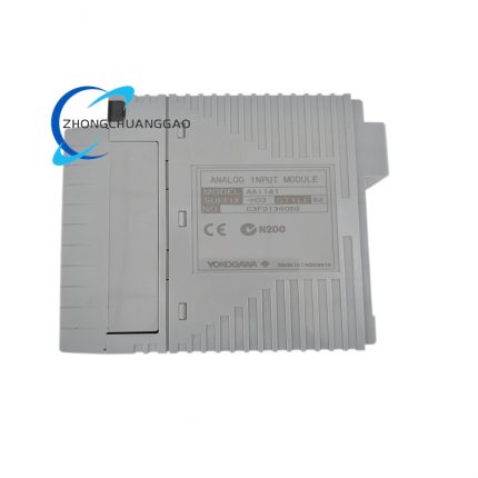
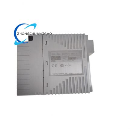
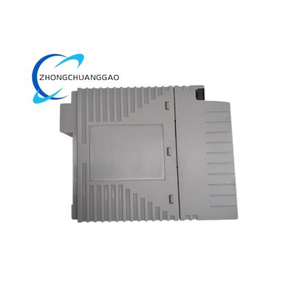
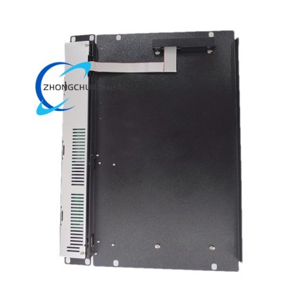
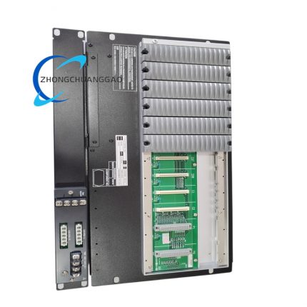
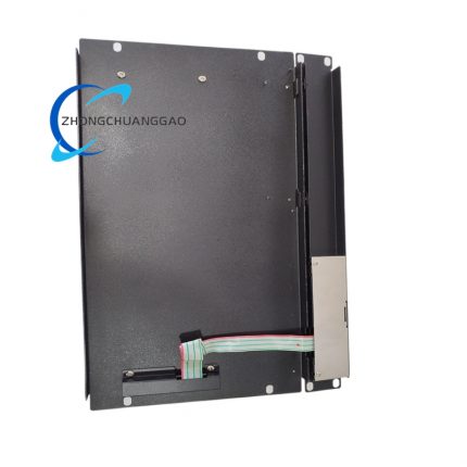
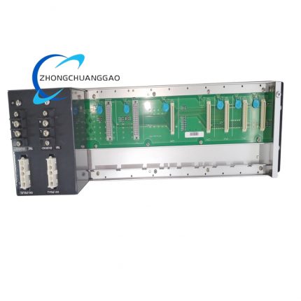
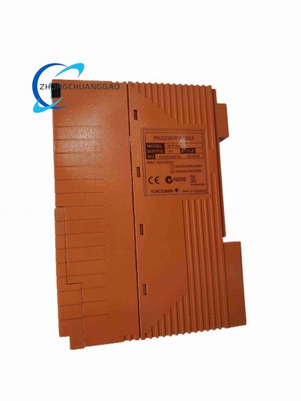
YOKOGAWA AAI543-S00

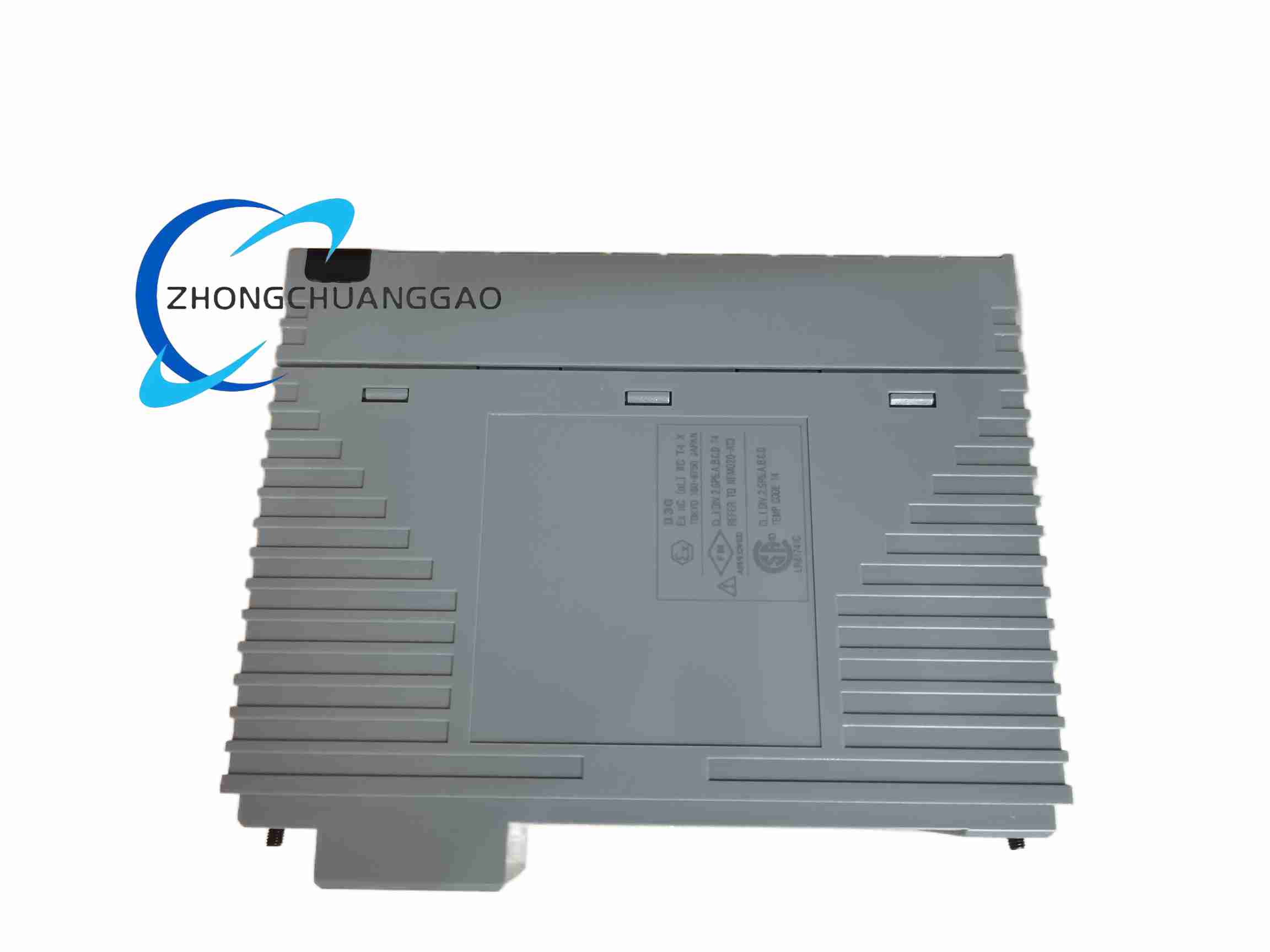
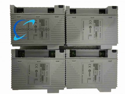
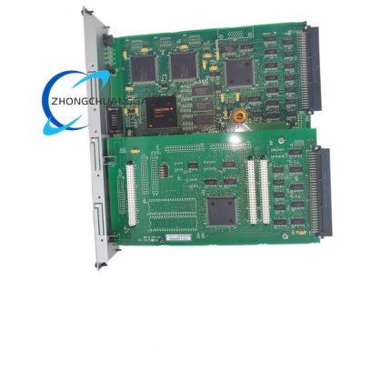
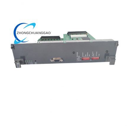
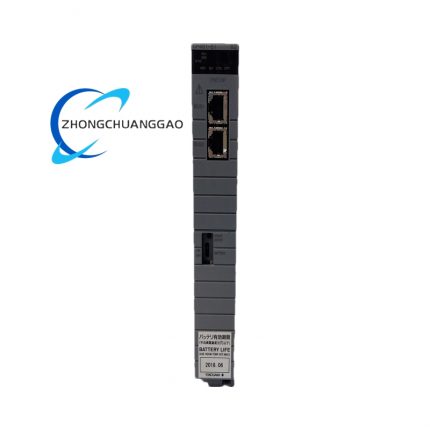
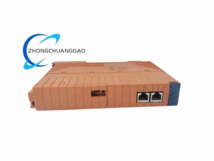
Product Introduction The AAI543-S00 S1 is a standard 16-channel analog current output module for the Yokogawa CENTUM VP and CENTUM CS 3000 DCS. It provides sixteen independently isolated 4 to 20 mA output channels for driving field actuators and control devices. The S00 suffix denotes the standard configuration without redundancy, and the S1 style code specifies the standard terminal and connector variant. The module converts FCS digital setpoints into precision analog current signals for continuous process control.

Category:
Description

Technical Specifications Output Channels: 16 channels, individually isolated Output Signal Range: 4 to 20 mA DC Output Accuracy: ±0.1% of full scale typical Allowable Load Resistance: 0 to 750 Ω Data Update Period: 10 ms Withstand Voltage: 1500 V AC between output and system, 1 minute Circuit-Open Detection: less than 0.65 mA Temperature Drift: ±16 µA per 10 °C Current Consumption: 230 mA at 5 V DC Operating Temperature: 0 to +55 °C Storage Temperature: -40 to +70 °C System Compatibility: CENTUM VP, CENTUM CS 3000 Mounting: FIO I/O rack (ANB10, ANR10, AFF50, AFV10, AFV30, AFV40)

Functional Features Sixteen galvanically isolated output channels deliver clean, independent current signals free from ground-loop interference. The 10 ms update period supports fast process loops. Open-circuit detection reports loop faults to the control system. Hot-swap capability allows module replacement without powering down the rack. Standard screw-clamp terminals (S1 style) provide secure, widely compatible field wiring.

Application Scenarios General-purpose analog output in refineries, chemical plants, water treatment facilities, food and beverage processing, pharmaceutical manufacturing, and boiler control systems. Drives control valves, I/P converters, variable-speed drives, damper actuators, and other 4 to 20 mA loop-powered or self-powered field devices.

Performance Parameters Output resolution: 16-bit equivalent Linearity: within ±0.05% of full scale Load regulation: within ±0.1% across 0 to 750 Ω Isolation resistance: greater than 100 MΩ at 500 V DC Ambient humidity: 5 to 95% RH non-condensing Vibration resistance: complies with IEC 60068-2-6 industrial standards

Material Composition UL 94 V-0 flame-retardant front panel and side moldings. Gold-plated backplane connector pins. Glass-epoxy PCB with conformal coating option. Internal toroidal isolation transformers. Steel EMC shielding plate.

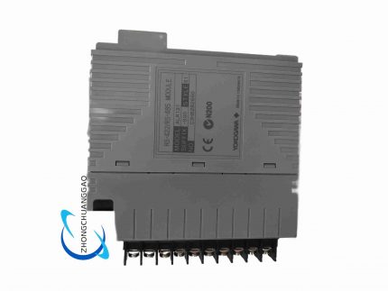
Structural Features Single-width plug-in card occupying one rack slot. Front panel features a module-status LED, a channel-activity LED array, and a captive retaining screw. Standard screw-clamp terminal block (M3 or M3.5) accepts 0.5 to 2.5 mm² wire. Rear connector interfaces with the rack backplane for ESB bus communication, 5 V DC power, and I/O signal routing.

Working Principle The FCS transmits 16-bit digital setpoint values to the module over the ESB bus. Each channel’s digital value is converted by a high-resolution DAC to an analog voltage, which a precision voltage-to-current converter translates into a 4 to 20 mA output. Per-channel DC-DC converters and optocouplers provide full galvanic isolation between channels and between the field side and system side. Open-loop monitoring circuitry detects current below the 0.65 mA threshold and raises a fault flag.

Installation Requirements Insert the module into a free slot of a compatible FIO node rack and tighten the retaining screw. Connect field wiring to the screw-clamp terminals per the channel wiring diagram, observing correct polarity. Confirm total loop load including wire resistance does not exceed 750 Ω. Apply 24 V DC field-side power where required. Verify ambient temperature is within 0 to +55 °C and the rack receives specified forced-air cooling.

Usage Precautions Do not exceed 750 Ω total load on any channel. Use shielded twisted-pair cable for all output loops and ground the shield at a single point. Keep analog wiring separated from high-voltage and high-frequency cables. Before hot-swapping, place the control loop in manual or bypass to avoid process upset. Do not connect external voltage sources to output terminals. Verify all 16 channels are configured in the engineering software before energizing field devices.

Reviews (0)

Reviews

There are no reviews yet.

Be the first to review “YOKOGAWA AAI543-S00”

Your email address will not be published. Required fields are marked *

Shipping and Delivery

MAECENAS IACULIS

Vestibulum curae torquent diam diam commodo parturient penatibus nunc dui adipiscing convallis bulum parturient suspendisse parturient a.Parturient in parturient scelerisque nibh lectus quam a natoque adipiscing a vestibulum hendrerit et pharetra fames nunc natoque dui.

ADIPISCING CONVALLIS BULUM

  • Vestibulum penatibus nunc dui adipiscing convallis bulum parturient suspendisse.
  • Abitur parturient praesent lectus quam a natoque adipiscing a vestibulum hendre.
  • Diam parturient dictumst parturient scelerisque nibh lectus.

Scelerisque adipiscing bibendum sem vestibulum et in a a a purus lectus faucibus lobortis tincidunt purus lectus nisl class eros.Condimentum a et ullamcorper dictumst mus et tristique elementum nam inceptos hac parturient scelerisque vestibulum amet elit ut volutpat.