Technical Specifications
- Input Power Specification: Single/3-phase 230 VAC ±10%, 50/60 Hz industrial mains
- Continuous Output Capacity: 4.6 kVA
- Continuous RMS Output Current: 12 A
- Peak Overload RMS Output Current: 30 A, maximum sustained overload duration 30 s
- Certified Hazardous Area Compliance: IEC 61241 Zone 2, Ex nA IIC T4
- Feedback Interface Reinforced Isolation Grade: 1500 Vrms reinforced insulation between power and signal circuits
- Supported Encoder Protocols: EnDat 2.1/2.2, HiRes, Sine/Cosine 1 Vpp, A/B/Z incremental encoder
- Communication Interfaces: Isolated SERCOS III, isolated RS485 Modbus RTU, isolated Ethernet/IP
- Control Modes: Position closed loop, speed closed loop, torque closed loop
- Digital I/O Channels: 16 isolated digital inputs, 8 isolated digital outputs
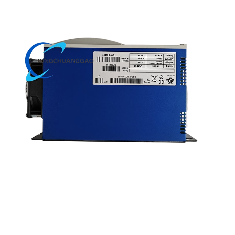
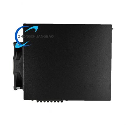
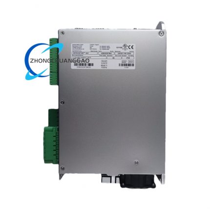
- Physical Outer Dimensions: 110 mm (W) × 260 mm (H) × 165 mm (D)
- Net Mass: 3.85 kg
- Enclosure Protection Grade: IP00, must install inside certified Zone 2 explosion-proof cabinet
- Continuous Operating Temperature: 0 ℃ ~ +45 ℃ non-condensing
- Storage Temperature Band: -20 ℃ ~ +70 ℃
- Operating Humidity Range: 5% ~ 90% RH without dew formation
Function Features
- All signal, encoder and communication circuits equipped with reinforced isolation barriers eliminating ignition spark risk for Zone 2 environments
- Full anti-corrosion internal acrylic conformal coating resistant to solvent vapor and light chemical mist
- Retains all native motion functions of standard CP310250: electronic cam, flying shear, electronic gearing
- Complete multi-stage hardware fault protection with isolated fault alarm output for external safety relay linkage
- Isolated SERCOS III motion bus eliminates cross-circuit leakage current in classified hazardous zones
- Encoder signal automatic calibration circuit modified with spark suppression filter components
- Firmware locked certified version complying with hazardous area safety operation standards, non-modifiable uncertified third-party firmware
- Dynamic braking circuit with surge suppression varistors to eliminate transient voltage spark generation
Performance Parameters
- Peak continuous torque overload capacity: 250% rated motor torque
- Position loop maximum bandwidth: 1200 Hz
- Speed loop maximum bandwidth: 800 Hz
- Position repeatability: ±1 encoder pulse
- SERCOS bus synchronization jitter: ≤0.5 μs
- Factory certified MTBF: 88,000 hours under Zone 2 rated operating ambient
Material Composition
- Outer housing: Cold rolled steel sheet with dual-layer anti-corrosion epoxy primer + matte black topcoat
- Power PCB substrate: High-temperature heavy copper FR-4 board with full insulated conformal coating
- Radiator assembly: Sealed extruded aluminum fin radiator with anti-oxidation passivation treatment
- Terminal blocks: Nickel-gold plated copper contacts, flame retardant PA66 anti-static plastic base
- Internal wiring insulation: Double-layer cross-linked polyethylene high voltage isolation wire
Structural Characteristics
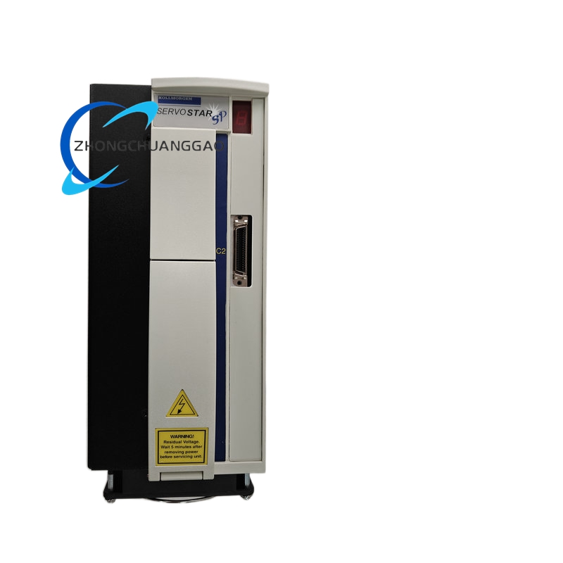
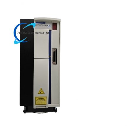
- Vertical DIN rail mounting form factor compatible with Zone 2 certified metal explosion-proof cabinets
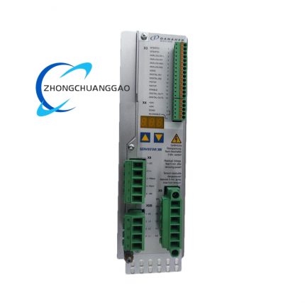
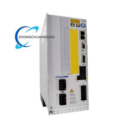
- Front panel sealed LED indicator assembly with dust-proof transparent protective cover
- High-voltage and low-voltage terminal regions fully separated by internal insulating partition plates
- All wiring entry points equipped with dedicated certified cable glands for explosion-proof cabinet matching
- Rear mounting lugs thickened for stable bolt fixation inside heavy-duty classified control enclosures
Working Principle
Three-phase mains AC power enters internal rectifier circuit to generate isolated DC bus voltage for insulated IGBT power switching modules. Motion position commands transmitted via galvanically isolated SERCOS III/Ethernet/IP bus, processed through reinforced isolation signal circuits to eliminate transient electrical sparks. PID closed-loop control logic calculates target three-phase motor current and outputs modulated power to explosion-proof servo motor windings. All digital I/O signals pass through optocoupler reinforced isolation barriers before entering internal logic circuits. Onboard surge suppression components absorb regenerative voltage spikes during motor deceleration to prevent ignition hazard in flammable gas environments. Motion parameters and fault records stored in sealed non-volatile flash memory with safety write protection lock.
Advantage Highlights
- Full IEC Zone 2 hazardous location certification for direct deployment in petrochemical, solvent processing and flammable dust production facilities
- Reinforced 1500 Vrms isolation across all signal circuits eliminates spark generation risk under all normal and minor fault operating states
- Dual-layer anti-corrosion housing and full-board conformal coating resist chemical vapor degradation long-term
- All communication and I/O ports galvanically isolated to block cross-circuit leakage current in classified zones
- Matches complete lineup of KOLLMORGEN Zone 2 certified explosion-proof servo motors without additional safety interface modules
- Surge suppressed dynamic braking circuit removes transient voltage ignition sources during high inertia deceleration
- Factory locked safety-certified firmware prevents unauthorized modification that would invalidate hazardous area certification
Applicable Industries
Offshore chemical processing platforms, solvent blending plants, paint and coating manufacturing, pharmaceutical solvent synthesis facilities, grain and feed flammable dust processing lines, alcohol distillation production equipment
Installation Requirements
- Install exclusively inside IEC certified Zone 2 explosion-proof metal control cabinet, vertical DIN rail fixed
- Maintain minimum 50 mm vertical radiator clearance above and below drive unit for convection cooling
- Use only certified explosion-proof cable glands for all wiring entry into classified cabinet housing
- Separate high-voltage power cables and isolated low-voltage signal cables in independent sealed cable conduits
- Cabinet grounding copper wire cross-section ≥4 mm², grounding resistance strictly controlled ≤3 Ω
- Mandatory cabinet internal forced cooling fan to maintain internal temperature below 40 ℃ continuous operation
Usage Precautions
- Cut mains power supply and wait 10-minute DC bus discharge period before opening cabinet wiring terminals in hazardous zones
- Do not substitute non-certified braking resistors, encoder cables or communication wiring; safety certification will be voided
- Regularly inspect internal conformal coating integrity every 6 calendar months for chemical vapor degradation
- Prohibit removal of front indicator dust-proof cover in classified production environments
- Any disassembly of internal isolation circuits or power modules invalidates all explosion-proof certification and factory warranty
- Do not store or operate unit in environments exceeding certified T4 temperature class rating




























Reviews
There are no reviews yet.