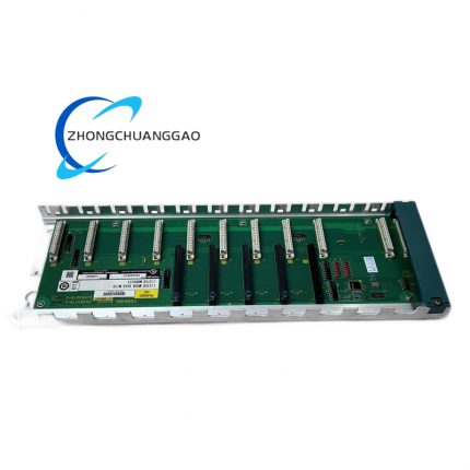
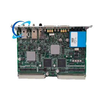
Delta Tau ACC‑24E2A4‑AXIS

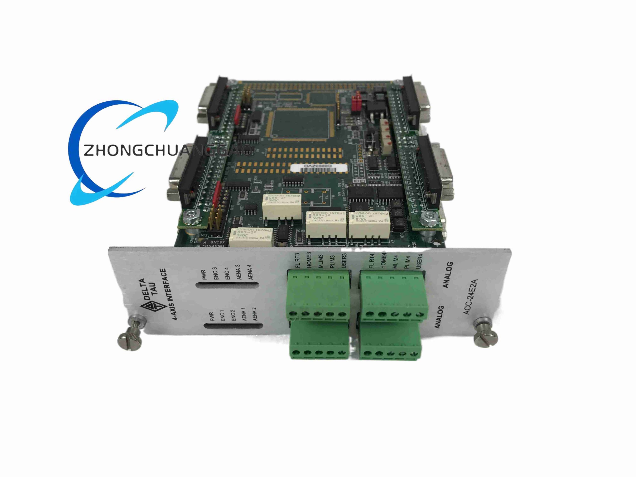
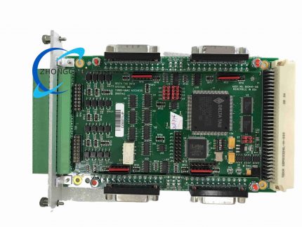
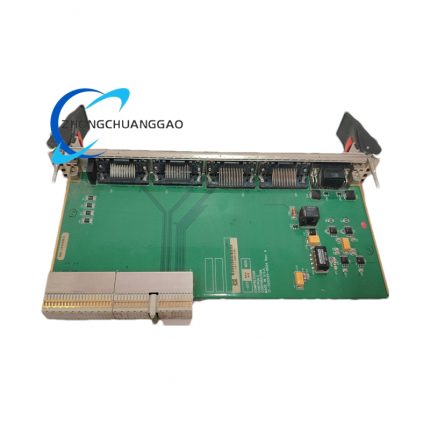
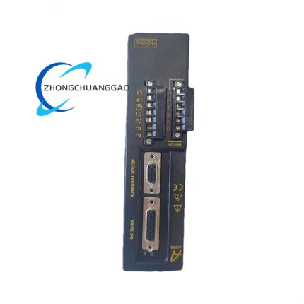
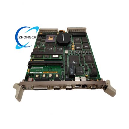
Product Description: This is a 3U rack‑mount servo axis expansion card belonging to Delta Tau UMAC motion control system series. It expands multi‑axis servo control capacity for UMAC and MACRO‑Station main controllers, delivering analog command signals and receiving encoder feedback signals to realize closed‑loop motion control for servo and stepper drives. The standard hardware supports 2 axes, and hardware upgrade option expands to full 4‑axis operation. Up to eight such boards can be installed on one UMAC host to reach 32 control axes in total.

Category:
Description
Technical Specifications:

Operating temperature ranges from 0°C to 45°C; storage temperature ranges from ‑25°C to 70°C; relative humidity maintains 10%‑95% non‑condensing. Physical dimension is 162.56 mm × 100 mm × 20.3 mm. Power is supplied from UBUS backplane. Command output supports ±10 V analog velocity/torque signal and pulse‑direction signal. Encoder input accepts differential and single‑ended TTL A/B/Z incremental encoder signals. Each axis provides 8 digital flag inputs and 2 digital flag outputs. Maximum 4 servo axes per single board. Communication interface adopts high‑speed UBUS backplane busManualsLib.

Functional Features:

Supports mixed control modes of analog voltage and pulse‑direction. Equipped with encoder loss detection function. Configurable differential/single‑ended encoder input through hardware jumper. Built‑in limit switch and flag signal processing circuit. Deterministic real‑time data transmission via UBUS backplane. Supports fault status feedback for each axis. Multiple cards can be stacked for axis quantity expansion. Compatible with most third‑party analog‑interface servo drives.

Application Scenarios:

Multi‑axis CNC machine tool control, semiconductor manufacturing equipment, multi‑joint robotic systems, automated assembly equipment, high‑speed packaging machinery, precision positioning platforms, and other industrial equipment requiring multi‑axis synchronous motion control.

Performance Parameters:

Servo clock can be configured by jumper setting. Encoder input frequency supports high‑speed incremental encoder feedback. Analog output accuracy matches PMAC2 motion control IC performance. Digital flag input works within 5 V‑24 V signal level range. System realizes microsecond‑level motion control cycle after backplane connection.

Material Composition:

FR‑4 printed circuit board, gold‑plated backplane connector, metal front panel with locking screw, industrial‑grade surface‑mount integrated circuits, terminal block connectors, through‑hole signal conditioning components, and EMC filtering components.

Structural Features:

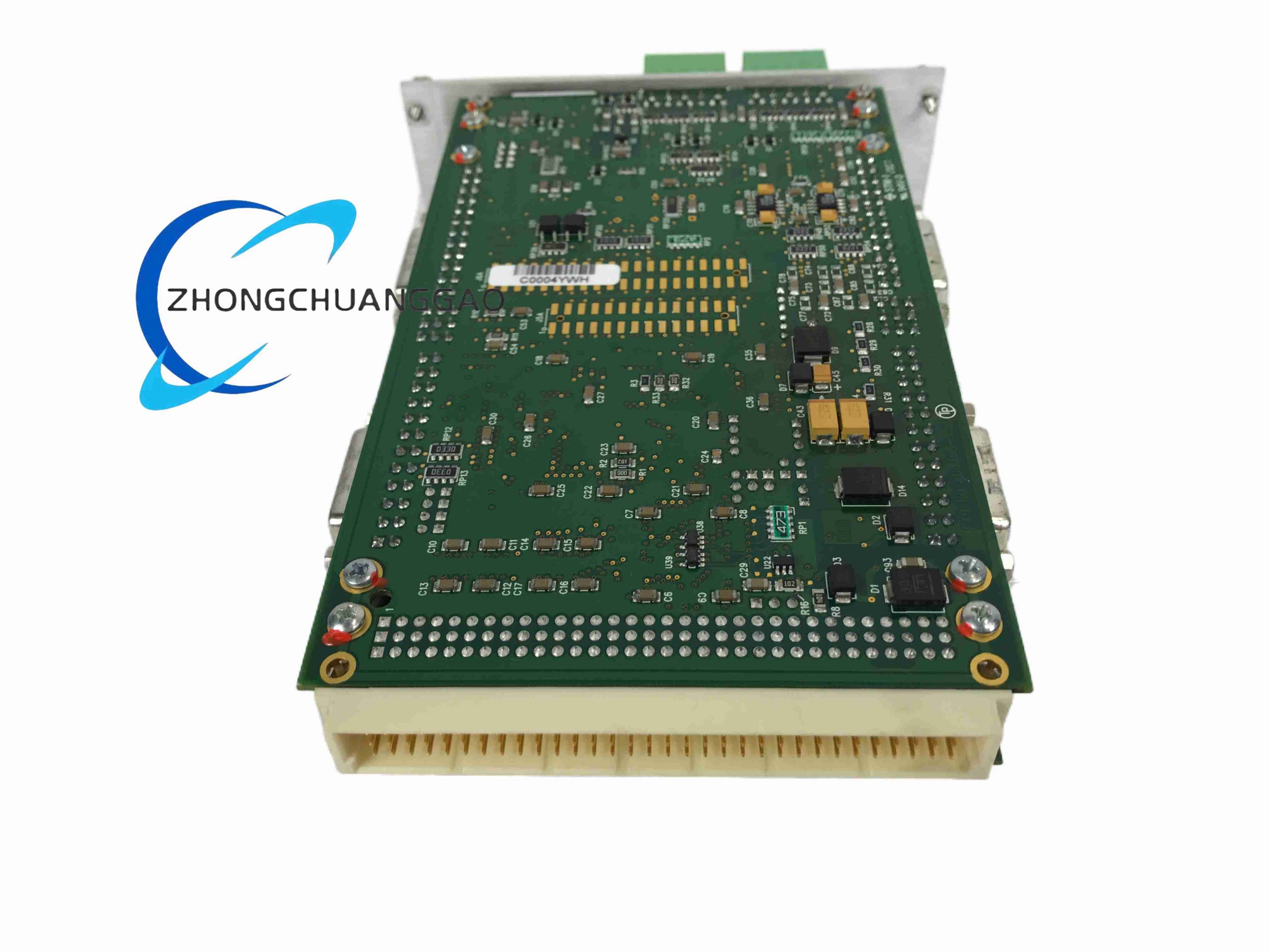
Standard 3U Eurocard form factor, single‑slot rack installation without option upgrade. Metal front panel with indicator windows and fixing screws. UBUS 96‑pin backplane header for internal controller communication. External signal is led out via removable terminal blocks. Piggyback sub‑board can be stacked to activate third and fourth axis channels, occupying two rack slots after installation of sub‑board.

Working Principle:

The board receives motion trajectory commands from UMAC main controller through UBUS backplane bus. The onboard PMAC2‑style servo IC converts digital motion instructions into ±10 V analog command or pulse‑direction signal and sends them to external servo drives. Encoder position feedback signal from motor returns to this board, and feedback data is transmitted back to main controller for position closed‑loop calculation. Digital limit and flag signals are sampled and uploaded to motion CPU for logic judgment and safety interlock execution.

Installation Requirements:

Install into standard 3U industrial rack and insert firmly into UMAC backplane slot. Tighten front‑panel locking screws to ensure reliable mechanical fixation. Configure hardware jumpers to select encoder signal mode and clock setting before power‑on. Complete wiring of servo command cable, encoder cable and limit‑flag signal cable. Confirm backplane power supply specification matches module requirement. ESD protection operation must be performed during installation. Avoid installing in positions directly adjacent to high‑power inverter modules to reduce electromagnetic interference.

Usage Notes:

Do not hot‑swap the module under powered‑on state. All signal wiring shall use shielded cables. Keep analog signal wiring away from high‑current power cables. Verify jumper configuration before power‑on to prevent hardware damage. Set axis assignment parameters in PMAC software after hardware installation. Check encoder power supply load capacity when connecting external encoders. Conduct full‑scale signal test after wiring completion. Operate within specified temperature and humidity range.

Reviews (0)

Reviews

There are no reviews yet.

Be the first to review “Delta Tau ACC‑24E2A4‑AXIS”

Your email address will not be published. Required fields are marked *

Shipping and Delivery

MAECENAS IACULIS

Vestibulum curae torquent diam diam commodo parturient penatibus nunc dui adipiscing convallis bulum parturient suspendisse parturient a.Parturient in parturient scelerisque nibh lectus quam a natoque adipiscing a vestibulum hendrerit et pharetra fames nunc natoque dui.

ADIPISCING CONVALLIS BULUM

  • Vestibulum penatibus nunc dui adipiscing convallis bulum parturient suspendisse.
  • Abitur parturient praesent lectus quam a natoque adipiscing a vestibulum hendre.
  • Diam parturient dictumst parturient scelerisque nibh lectus.

Scelerisque adipiscing bibendum sem vestibulum et in a a a purus lectus faucibus lobortis tincidunt purus lectus nisl class eros.Condimentum a et ullamcorper dictumst mus et tristique elementum nam inceptos hac parturient scelerisque vestibulum amet elit ut volutpat.