Technical Specifications PROFIBUS Side:
- PROFIBUS Mode: DP Slave (DP Device)
- PROFIBUS Baud Rate: 9600 bit/s to 12 Mbit/s, automatic detection
- PROFIBUS Address: 0 to 125, set via rotary switches
- Cyclic Input Data: up to 244 bytes
- Cyclic Output Data: up to 244 bytes
- Total Cyclic I/O: up to 488 bytes
- Acyclic Data: DP-V1 Class 1 and Class 2 supported
- Features: Sync, Freeze, Watchdog
- Configuration: GSD file provided
- Connector: 1× D-sub 9-pin female
Serial / CAN Side:
- Serial Interface: RS-232, RS-422, RS-485 (software-selectable)
- Serial Baud Rate: 1.2 kbit/s to 57.6 kbit/s (depending on variant)
- Serial Mode: full-duplex (RS-232/422) or half-duplex (RS-485)
- CAN Interface (where fitted): CAN 2.0A/2.0B, 20 kbit/s to 1 Mbit/s
- Protocol Support: generic ASCII, Modbus RTU, proprietary serial, CANopen, custom CAN
- Connector: D-sub 9-pin or terminal block (variant-dependent)
Power and Environment:
- Supply Voltage: 24 V DC ±10%
- Current Consumption: approximately 100 to 250 mA at 24 V DC
- Operating Temperature: 0 to +55 °C (or -25 to +55 °C depending on revision)
- Storage Temperature: -40 to +85 °C
- Protection Class: IP20
- Mounting: DIN-rail EN 50022
- Certification: CE, UL, cUL
Functional Features Transparent protocol conversion connects any serial or CAN device to PROFIBUS DP without firmware changes to the device. Visual configuration through the Anybus Configuration Manager supports frame building, transaction scheduling, and data mapping. Automatic PROFIBUS baud rate detection eliminates manual speed matching. Supports Modbus RTU master mode for querying serial instruments. Produce/Consume and Request/Response transaction modes handle both cyclic and event-driven data exchange. Save/Load function replicates configurations across identical installations.
Application Scenarios Integration of barcode scanners, weigh scales, RFID readers, laboratory analyzers, variable-frequency drives, sensors, and legacy PLCs into PROFIBUS DP networks. Used in automotive assembly, food and beverage packaging, pharmaceutical manufacturing, material handling, and water treatment where serial or CAN devices must exchange data with a PROFIBUS-based controller.
Performance Parameters PROFIBUS cyclic I/O: 244 bytes input + 244 bytes output Serial transaction capacity: up to 128 transactions Configuration update: via USB or serial configuration port Watchdog: configurable timeout for communication monitoring Isolation: galvanic isolation between network ports and power EMC: EN 61000-6-2 immunity, EN 61000-6-4 emission, EN 55022 Class A Humidity: 5 to 95% RH non-condensing
Material Composition Blue ABS/PC flame-retardant housing. Gold-plated D-sub connectors. Steel DIN-rail clip. Glass-epoxy PCB with surface-mount components. Internal DC-DC isolation converters and optocouplers.
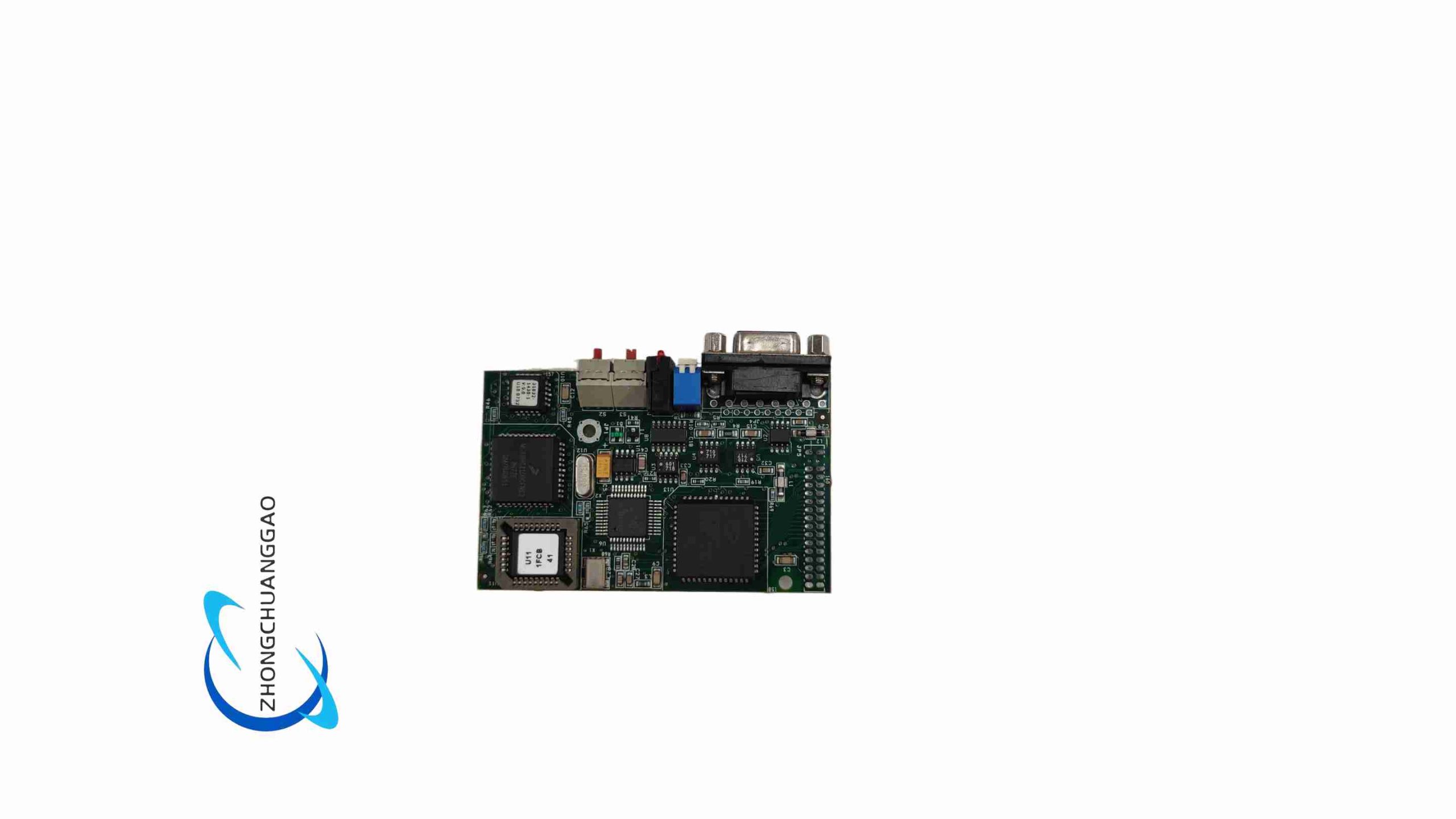
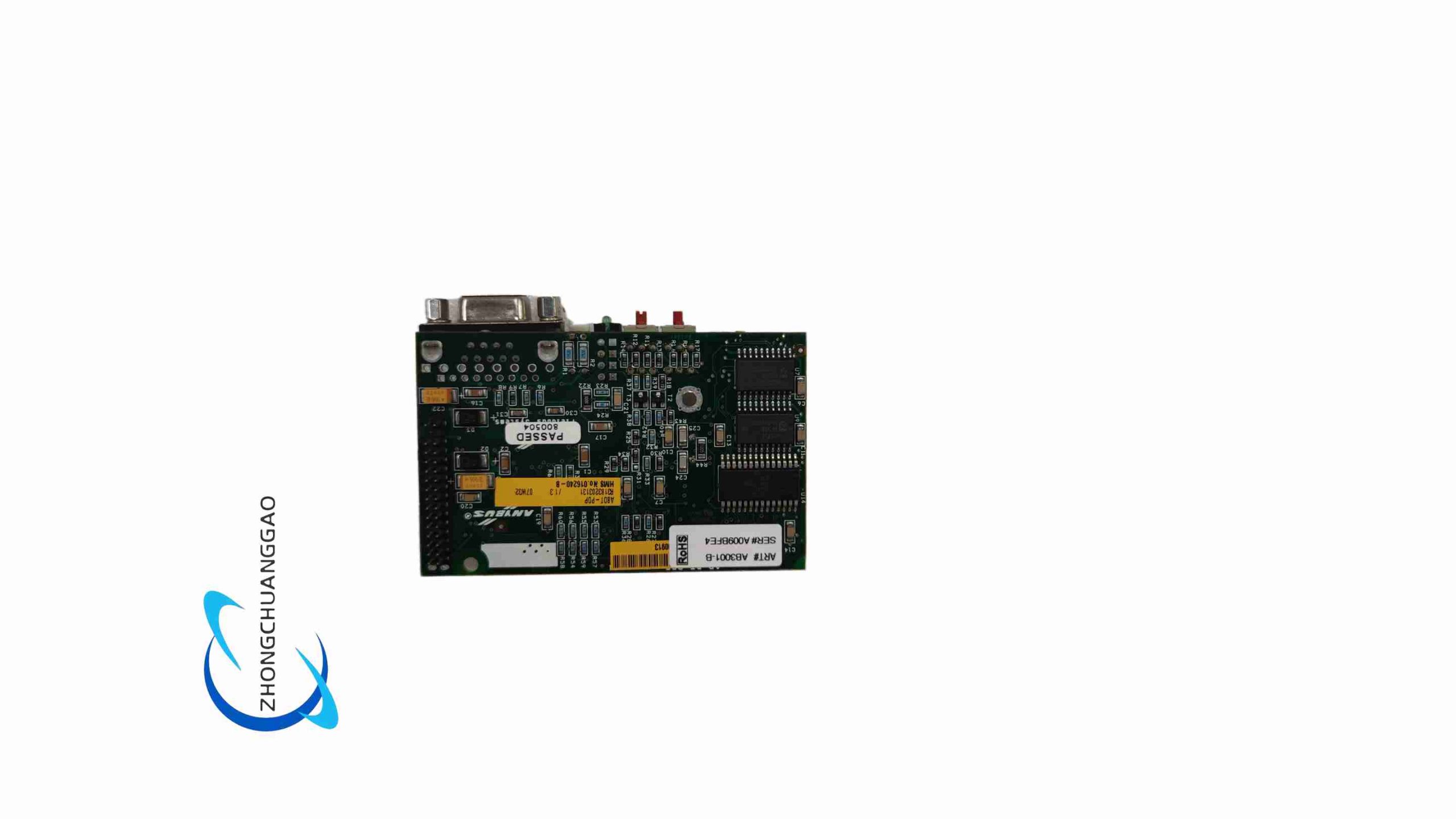
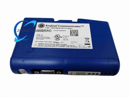
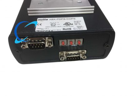
Structural Features Compact DIN-rail mount enclosure. Front panel includes rotary PROFIBUS address switches, status and fault LEDs, a serial/CAN connector, and a 2-pin power connector. PROFIBUS connector is located on the side or front depending on revision. Internal architecture uses a dedicated network processor for the PROFIBUS stack and a separate processor for serial/CAN protocol handling.
Working Principle The gateway acts as a PROFIBUS DP slave on the fieldbus side and as a serial/CAN master or monitor on the device side. Data received from the serial or CAN port is parsed according to the configured transaction rules and stored in an internal I/O buffer. The PROFIBUS interface maps this buffer to cyclic input data for the master. Output data written by the PROFIBUS master is placed in the buffer and transmitted out the serial or CAN port according to the configured frame format and trigger condition. The conversion is fully transparent and requires no PLC function blocks.
Installation Requirements Mount on a standard DIN rail inside an IP20-rated cabinet. Connect 24 V DC power with correct polarity. Wire the PROFIBUS DP cable to the D-sub 9-pin connector and install 120 Ω termination resistors at both network ends. Connect the serial or CAN device using shielded cable appropriate to the interface. Set the PROFIBUS address with the rotary switches. Import the GSD file into the PLC engineering environment and configure the I/O data length to match the gateway configuration.
Usage Precautions Do not exceed the rated supply voltage range. Ensure PROFIBUS and serial/CAN buses are properly terminated. Keep communication cables separated from power cables. Use shielded twisted-pair cable and ground shields at one end. Verify the serial baud rate, data bits, parity, and stop bits match the connected device exactly. Do not connect multiple bus masters to an RS-485 segment without a defined arbitration scheme. Save the configuration file for backup and replication.



























Reviews
There are no reviews yet.