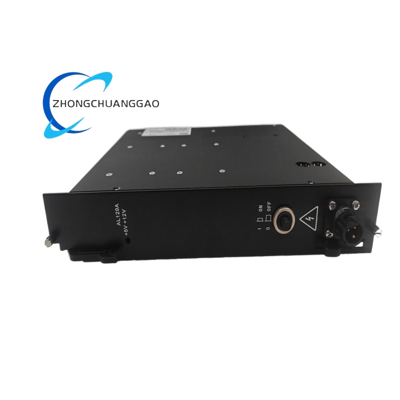
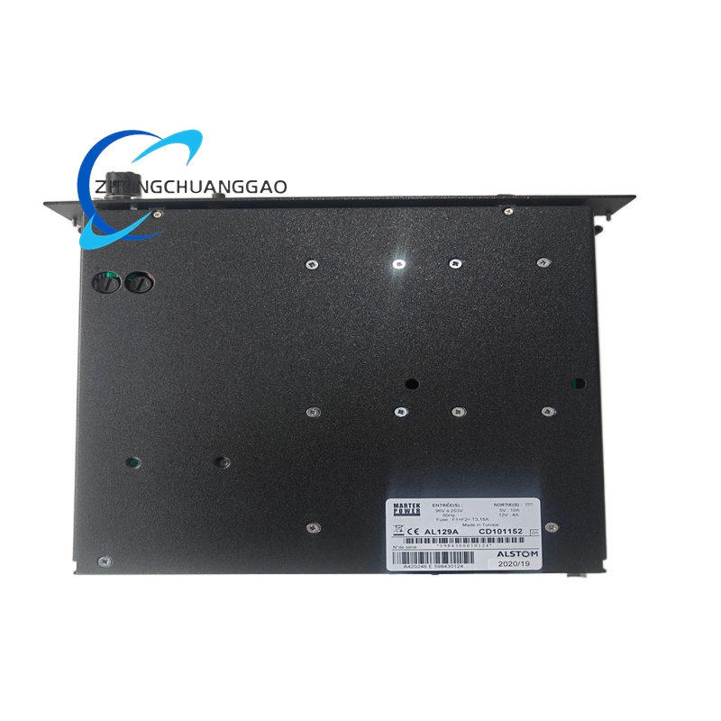
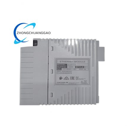
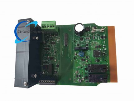
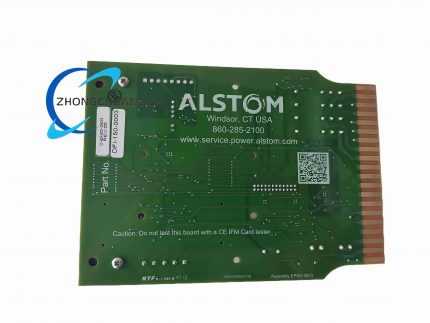
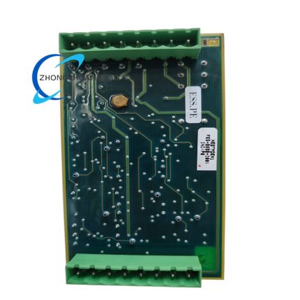
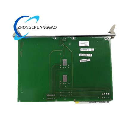
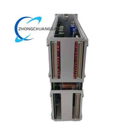
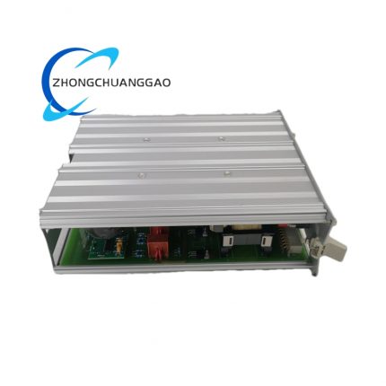
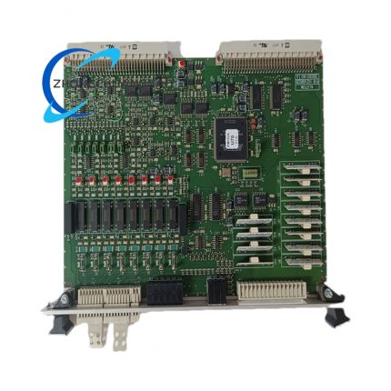
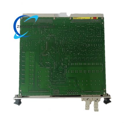
Core Technical Specifications
- Safety Integrity Level: IEC 61508 SIL 3
- Output Channel Quantity: 2 independent isolated safety relay output channels
- Relay Construction: Force-guided mechanically linked safety relays (mechanical contact interlock verification)
- Contact Rated Capacity: 2 A continuous resistive load at 24 V DC auxiliary supply
- Maximum Relay Operating Actuation Time: <5 ms
- Input/Output Isolation Voltage: 2000 V AC dielectric withstand
- Backplane Communication Interface: Dedicated Turbine Guard high-speed parallel system bus
- Auxiliary Supply Voltage Range: 24 V DC to 250 V DC wide-range universal auxiliary power
- Operating Temperature Range: 0 °C to +60 °C
- Storage Temperature Range: -30 °C to +70 °C
- Ingress Protection Class: IP20 (cabinet rack installation only)
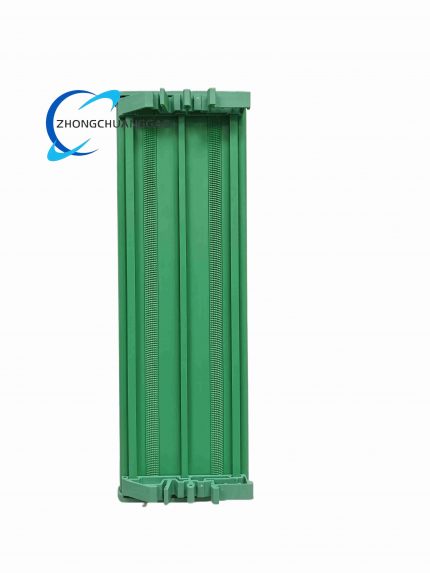
- Installation Standard: EN 60715 DIN rail mount / 19-inch standard rack card mount
- Module Physical Dimensions: 128 mm (H) × 45 mm (W) × 110 mm (D)
- Net Weight: 0.48 kg
Functional Features
- Dual redundant safety output channels for redundant emergency shutdown circuit architecture
- Real-time relay contact wear self-diagnosis with front-panel fault LED indicator
- Force-guided relay mechanical interlock prevents simultaneous open/closed contact failure
- Hardware fault latching logic retains trip status until manual system reset
- Full bus communication fault detection with automatic fail-safe contact de-energization
- Hot-swappable module replacement with no full system power shutdown required
Working Principle
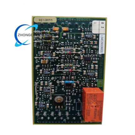
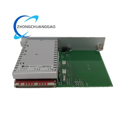
The Turbine Guard main controller transmits digital safety trip signals via the rack backplane bus to the AL129A CD101152 module’s internal logic circuit. Upon receiving a trip command, the control circuit energizes the force-guided safety relay coils, mechanically switching the output contact state to cut control power to critical turbine equipment. On-board diagnostic circuits continuously monitor relay coil continuity and contact mechanical linkage integrity; any detected fault triggers a persistent fault alarm signal transmitted back to the main system controller.
Material & Structural Characteristics
- Main circuit board: FR-4 high-voltage flame-retardant PCB with reinforced isolation barriers
- Relay housing: High-temperature thermoplastic flame-resistant safety enclosure
- Module outer casing: ABS anti-static industrial plastic with matte gray finish
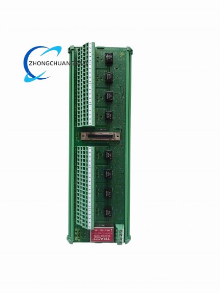
- Terminal block: Gold-plated screw terminal blocks for field wiring connections
- Backplane connector: Tin-plated spring-loaded edge connector for rack bus connection
Core Advantages & Highlights
- SIL 3 safety certification meets global power plant turbine protection functional safety standards
- Force-guided relay design eliminates dangerous contact sticking failure modes
- Dual independent output channels support redundant safety shutdown circuit design
- Wide universal auxiliary power supply eliminates separate power conversion hardware
- On-board continuous self-diagnosis reduces scheduled safety inspection frequency
Applicable Industries
Thermal power plant steam turbine protection, combined-cycle gas turbine safety control, hydroelectric generator rotating machinery monitoring, industrial large compressor safety interlock systems, nuclear power auxiliary rotating equipment protection
Installation Mandatory Requirements
- Install only within ventilated electrical control cabinets; ambient temperature must never exceed 60 °C
- Separate safety trip wiring from analog sensor signal wiring by minimum 20 cm physical distance
- Auxiliary power supply must incorporate certified SIL3 safety-grade surge suppression
- Secure DIN rail mounting with locking clip to prevent module dislodging under seismic vibration
- Complete full safety loop functional testing after every module replacement or wiring modification
Operation & Maintenance Precautions
- Do not connect inductive loads without parallel freewheeling diode surge protection
- Conduct annual relay contact resistance testing to identify wear degradation
- Avoid exposing module to hydrogen sulfide, sulfur dioxide, or other corrosive industrial gases
- Never bypass module safety output channels during system operational commissioning
- Replace relays after 100,000 mechanical switching cycles to maintain SIL3 safety rating
Reviews
There are no reviews yet.