Technical Specifications
- Mounting Standard: 35 mm DIN top hat rail vertical mounting
- Overall Dimensions (W × H × D): 76 mm × 110 mm × 75 mm
- Net Unit Weight: 0.32 kg
- Power Supply Input: 24 V DC ±10%
- Onboard Digital Input Points: 6 sink/source compatible DC 24 V discrete inputs
- Digital Input Signal Rating: 24 V DC, input current 7 mA per channel
- Onboard Digital Output Points: 6 transistor DC sinking outputs
- Digital Output Rated Load: 0.5 A per channel, total combined output current maximum 2 A
- Internal Program Memory Capacity: 4 K steps ladder logic program storage
- Data Register Capacity: 256 16-bit general purpose data registers
- Communication Interfaces: 1 × RS232 programming port, 1 × isolated RS485 Modbus RTU slave port
- Minimum Program Scan Cycle Time: 0.5 ms per 1 K program steps
- Timer Range: 0.1 s–9999 s adjustable timing value
- Counter Range: 16-bit up/down counter maximum value 32767
- Operating Ambient Temperature: 0 °C to +55 °C
- Storage Temperature Band: -20 °C to +70 °C
- Relative Humidity Operating Range: 5%–95% RH, non-condensing
- Isolation Rating: 500 V AC between power supply and I/O signal circuits
- Compliance Certifications: CE industrial control standard
Function Features
- Integrated all-in-one 6DI / 6DO digital terminal layout eliminates external I/O expansion modules for simple sequential control tasks
- Dual serial communication ports for offline programming via RS232 and upper system data exchange via Modbus RTU RS485
- Complete basic logic instruction set including contact logic, timer, counter, comparison, data transfer arithmetic commands
- Transistor DC output design supports high-speed pulse output for stepper motor low-speed positioning control
- Built-in power failure data retention circuit stores counter values and data registers for minimum 7 days without external power supply
- Front panel dedicated LED indicators for each discrete input/output channel, power supply and run/fault operating state
- Hardware overcurrent short-circuit protection on all transistor output channels to prevent internal circuit burnout from field wiring faults
- Compact ladder diagram programming environment compatible with official KOYO programming software for Windows operating systems
Performance Parameters
- Full 4 K program memory single scan cycle maximum duration: 2 ms
- Digital input signal filter delay configurable range: 0 ms–100 ms
- RS485 Modbus RTU communication baud rate options: 2400 / 4800 / 9600 / 19200 bps
- High-speed pulse output maximum frequency: 10 kHz single channel
- Data register retention period without power supply: 7 days minimum
- Input channel signal response latency: ≤ 0.1 ms without filter delay
Material Composition
- Outer housing: Black flame-retardant ABS industrial plastic enclosure
- Internal circuit substrate: Single-layer FR4 flame retardant printed circuit board
- I/O terminal blocks: PA66 glass-filled thermoplastic with tin-plated copper screw terminals
- Communication connectors: D-Sub 9-pin RS232 programming port with gold-plated pins
- Power and output drive components: SMD industrial transistors, power regulation IC chips
- DIN rail fixture: Integrated plastic locking clip with metal spring anti-slip structure
Structural Characteristics
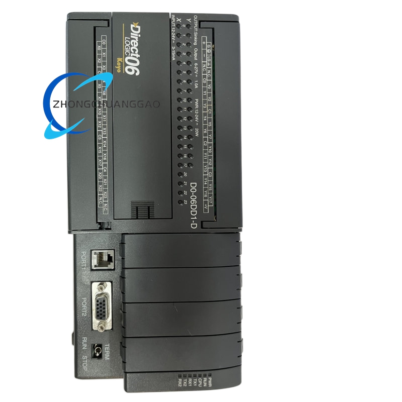
- Slim vertical DIN rail all-in-one integrated structure without separate expansion base
- Top panel layout: 24 V DC power supply terminal block, RS485 communication terminal block
- Bottom panel layout: 6 digital input terminals, 6 digital transistor output terminals
- Front panel layout: Channel-by-channel I/O status LED array, RUN/ERR system status LED indicators, RS232 D-Sub programming port
- Fully enclosed plastic casing with small convection vent slits for passive cooling
- IP20 protection rating, restricted to installation inside sealed industrial control cabinets
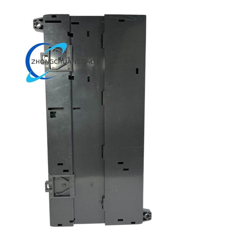
- Tool-free mounting and disassembly via side plastic DIN rail lock clip
Working Principle
- 24 V DC input power passes through EMI filter and overvoltage protection circuit to supply CPU, I/O drive and communication circuit modules
- Discrete 24 V DC sensor input signals enter isolated input conditioning circuits, converted into digital logic levels for CPU register storage
- Central processing unit executes ladder logic program line by line within fixed scan cycle, processing timer, counter and arithmetic instructions sequentially
- Calculated digital output logic states drive onboard sinking transistor circuits to switch external 24 V DC actuator loads
- RS232 port establishes bidirectional communication with PC programming software for program upload, download and online monitoring
- Isolated RS485 port transmits holding register data to upper HMI or supervisory PLC via Modbus RTU slave protocol
- Non-volatile backup circuit maintains counter accumulated values and production data registers during temporary power outage events
- Hardware fault detection circuit monitors output channel short-circuit conditions; disables corresponding transistor drive and lights ERR alarm LED upon overcurrent detection
Advantage Highlights
- All-in-one integrated 6DI/6DO compact design reduces cabinet space and auxiliary wiring cost for simple automation equipment
- Dual serial communication ports support both offline programming and factory network Modbus data collection simultaneously
- Built-in high-speed pulse output function enables low-power stepper motor positioning without extra motion control modules
- Seven-day power-off data retention eliminates recipe and counter value loss during short production power outages
- Hardware independent short-circuit protection per output channel avoids full PLC shutdown caused by single field wiring fault
- Low power consumption generates minimal heat, eliminating need for cabinet auxiliary cooling fans
- Simplified ladder logic programming reduces commissioning learning curve for basic sequential control applications
Applicable Industries
Small automated conveyor lines, simple packaging auxiliary equipment, small material sorting machinery, water pump sequential control panels, ventilation fan interlock control, automated gate and door sequential control systems, light textile small auxiliary machinery
Installation Requirements
- Vertically attach unit to standard 35 mm DIN top hat rail and fully engage side locking clip
- Reserve minimum 30 mm vertical clearance above and below casing for convection cooling airflow
- Install only inside IP54 or higher rated sealed control cabinets to block dust and moisture ingress
- Separate high-current actuator load wiring and low-current sensor/communication cables into isolated cable trunking with minimum 5 cm separation gap
- Connect cabinet protective earth busbar to control system 24 V DC power supply negative common grounding point
- Do not mount adjacent to high-power variable frequency drives generating strong electromagnetic interference
- RS485 Modbus bus wiring must install 120 Ω termination resistor at two bus endpoints for communication stability
Usage Notes
- Set digital input filter delay parameter matching connected sensor mechanical bounce characteristics before program operation
- Do not connect output channel load current exceeding 0.5 A per single transistor output to avoid permanent drive transistor burnout
- Complete program backup to local PC storage before executing firmware version upgrade procedures
- RS485 communication cable must use shielded twisted pair cable with single-point shielding grounding at cabinet earth bar
- Avoid continuous ambient operating temperature exceeding +55 °C to shorten internal backup capacitor service life
- Quarterly clean casing convection vent slits with dry compressed air to remove accumulated dust blocking heat dissipation
- Do not modify internal PCB circuit traces; all logic adjustments must be completed via official programming software ladder diagram editing



























Reviews
There are no reviews yet.