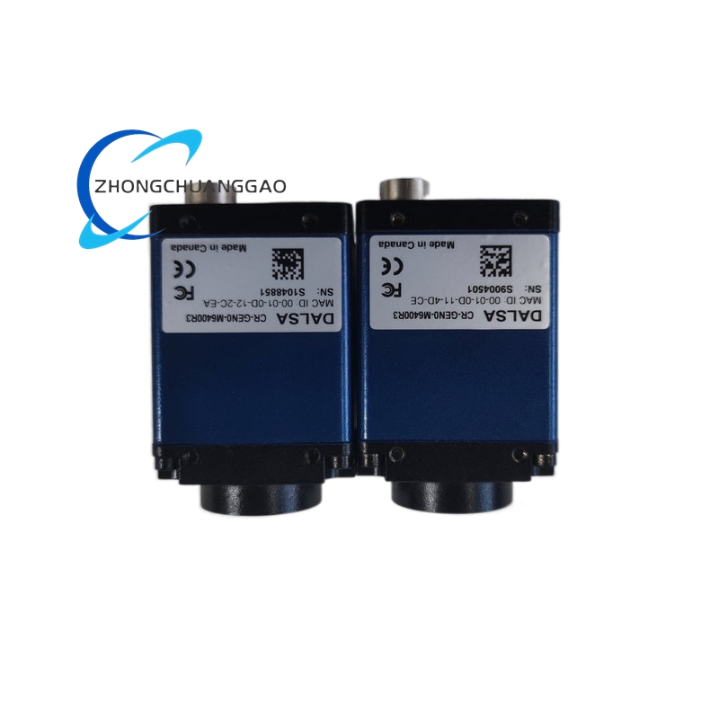
DALSA CR-GEN0-M6400R3

Product Overview

DALSA CR-GEN family monochrome line scan industrial camera, model M6400R3 featuring 6400 single-line CCD sensor array, engineered for high-speed continuous web inspection, precision surface defect detection and high-resolution dimensional measurement on moving production material substrates.
Category:
Description

Model Series

DALSA CR-GEN Line Scan Industrial Camera Series

Technical Specifications

  • Sensor Type: Linear CCD Image Sensor
  • Effective Pixel Count: 6400 monochrome active pixels
  • Pixel Size: 7.0 μm × 7.0 μm square pixel geometry
  • Full Dynamic Range: 72 dB optical dynamic range
  • Bit Depth: 12-bit digital pixel output
  • Max Line Scan Frequency: 68 kHz continuous line rate
  • Lens Mount Standard: C-Mount industry standard lens interface
  • Digital Data Interface: Camera Link Full high-speed data output
  • Power Supply Input: 24 V DC nominal camera power, 12 W maximum power consumption
  • Mechanical Dimensions: 145 mm (L) × 82 mm (W) × 62 mm (H)
  • Weight: 0.78 kg complete camera assembly

Performance Parameters

  • Signal-to-Noise Ratio: 64 dB maximum sensor SNR
  • Exposure Time Adjustment Range: 1 μs – 10,000 μs programmable electronic shutter
  • Analog Gain Adjustment Range: -3 dB to +32 dB software configurable gain
  • Trigger Modes: Hardware line trigger, software free-run continuous scan, encoder synchronous external trigger
  • Pixel Non-Uniformity: < 0.5% full scale pixel response variation
  • Operating Temperature Range: -20 °C to +50 °C
  • Storage Temperature Range: -40 °C to +70 °C

Material Composition

  • Camera Housing: Die-cast aluminum alloy enclosure with hard black anti-reflection anodized coating
  • Optical Window: Anti-reflection coated tempered borosilicate glass protective front window
  • Internal Sensor Substrate: FR-4 rigid PCB with CCD sensor chip bonded to precision aluminum heat spreader
  • Internal Wiring: Shielded twisted-pair high-speed digital signal cables with EMI shielding braids
  • Connector Housings: Polyamide PA66 flame-resistant plastic Camera Link and power connector shells
  • Mounting Hardware: Stainless steel corrosion-resistant mounting screw fasteners and alignment brackets

Structural Features

  • Compact sealed aluminum die-cast housing with IP30 dust protection rating for industrial production line deployment
  • C-Mount lens flange with precision mechanical alignment tolerances for interchangeable industrial inspection lenses
  • Dual rear panel connectors: Camera Link full digital data output port and 24 V DC power input connector
  • Integrated internal passive heat spreader bonded to CCD sensor to maintain stable sensor temperature during continuous high-line-rate operation
  • Built-in hardware trigger input terminal block for synchronous encoder signal connection with production line transport machinery
  • Internal EMI shielding partitions separating analog sensor circuitry from high-speed digital data transmission circuits

Working Principle

  1. External 24 V DC stabilized industrial power supply feeds camera internal multi-stage power regulation circuits supplying CCD sensor, analog signal amplifier and digital data processing logic.
  2. Light reflected from moving production web substrate passes through C-mount inspection lens and anti-reflection protective glass window onto linear 6400-pixel CCD sensor array.
  3. CCD sensor converts incident optical light intensity into proportional analog electrical charge signals; analog amplifier stage applies user-programmable gain adjustment to optimize signal level for low-light inspection environments.
  4. Analog pixel signals are digitized to 12-bit high-resolution digital pixel values via onboard analog-to-digital conversion circuitry; digital pixel data buffered to internal high-speed memory cache.
  5. Buffered line scan pixel data transmits continuously via Camera Link Full high-speed digital interface to compatible industrial frame grabber board installed within machine vision host computer.
  6. External encoder hardware trigger signal synchronizes line scan capture speed with production line web transport velocity to eliminate image stretching/compression distortion on moving material surfaces.

Core Function Features

  1. 6400 linear pixel high-resolution CCD sensor for ultra-fine surface defect detection on continuous web substrates
  2. 68 kHz maximum continuous line scan frequency supporting high-speed production line inspection throughput
    1. 12-bit high dynamic range digital pixel output for capturing subtle low-contrast surface flaws
    2. Programmable electronic shutter with exposure range 1 μs–10,000 μs to adapt variable ambient lighting intensity
    3. Software adjustable analog gain (-3 dB ~ +32 dB) for low-brightness dark chamber inspection environments
    4. Multi-mode synchronous trigger interface compatible with conveyor rotary encoder signals to eliminate motion image distortion
    5. Standard Camera Link Full high-speed interface with full compatibility with DALSA, NI, EURESYS industrial frame grabber series
    6. Sealed die-cast aluminum housing with IP30 dust resistance for workshop long-cycle non-stop operation

    Advantage Highlights

    1. 6400 ultra-long linear pixel array realizes single-scan full-width coverage of wide web materials, eliminating multi-camera splicing cost
    2. Max 68 kHz high line rate supports ultra-fast production line speed without sacrificing inspection resolution
    3. 72 dB wide optical dynamic range simultaneously identifies bright reflective scratches and dark tiny pits on material surfaces
    4. Built-in passive sensor heat spreader stabilizes CCD operating temperature, avoiding pixel drift and image brightness fluctuation during long runtime
    5. Standard C-Mount interface supports all mainstream industrial fixed-focus, telecentric, line scan dedicated lenses with flexible optical matching
    6. Hardware encoder synchronous trigger function ensures pixel geometric accuracy for dimensional measurement quality control
    7. Compact single-body integrated design omits external cooling auxiliary equipment, saving machine vision cabinet installation space

    Applicable Industries

    Printed Circuit Board PCB Surface Defect Inspection, Lithium Battery Electrode Coating Web Inspection, Paper & Film Continuous Surface Scanning, Metal Foil Strip Defect Detection, Textile Fabric Weaving Defect Inspection, Glass Sheet Flat Surface Quality Testing, Solar Cell Silicon Wafer Line Scan Inspection

    Installation Requirements

    1. Mount camera body on rigid stainless steel adjustable fixture bracket, lock all positioning screws with torque 0.7 N·m
    2. Maintain vertical perpendicular alignment between camera optical axis and moving material surface, deviation angle limited within ±0.1°
    3. Install matched C-Mount lens; evenly tighten lens locking ring to prevent lens displacement under equipment vibration
    4. Separate Camera Link high-speed signal cable from high-power AC drive wiring with minimum 15 cm isolation clearance to block EMI noise
    5. Supply regulated 24 V DC power with voltage fluctuation strictly controlled within ±5% rated range
    6. Reserve 20 mm surrounding clearance around camera housing for natural convection heat dissipation

    Operation & Maintenance Precautions

    1. Strictly avoid direct impact or scratch on front anti-reflection optical window; only use lint-free optical cleaning cloth with anhydrous ethanol for surface decontamination
    2. Do not operate camera under ambient temperature exceeding +50 °C continuously for more than 4 hours to prevent CCD sensor thermal aging
    3. Disconnect power before plugging/unplugging Camera Link and power connectors to eliminate hot-plug transient surge damage
    4. Regularly clean internal heat spreader ventilation gap every 6 months in dusty production workshops to avoid heat accumulation
    5. Never disassemble sealed camera housing without factory authorization; disassembly will void official calibration and warranty certification
    6. Shield all signal cables with full metal shielding layer, connect shielding braid to equipment protective earth terminal
    7. Perform pixel uniformity calibration via DALSA Sapera Vision Software every 12 months to maintain consistent inspection precision
Reviews (0)

Reviews

There are no reviews yet.

Be the first to review “DALSA CR-GEN0-M6400R3”

Your email address will not be published. Required fields are marked *

Shipping and Delivery

MAECENAS IACULIS

Vestibulum curae torquent diam diam commodo parturient penatibus nunc dui adipiscing convallis bulum parturient suspendisse parturient a.Parturient in parturient scelerisque nibh lectus quam a natoque adipiscing a vestibulum hendrerit et pharetra fames nunc natoque dui.

ADIPISCING CONVALLIS BULUM

  • Vestibulum penatibus nunc dui adipiscing convallis bulum parturient suspendisse.
  • Abitur parturient praesent lectus quam a natoque adipiscing a vestibulum hendre.
  • Diam parturient dictumst parturient scelerisque nibh lectus.

Scelerisque adipiscing bibendum sem vestibulum et in a a a purus lectus faucibus lobortis tincidunt purus lectus nisl class eros.Condimentum a et ullamcorper dictumst mus et tristique elementum nam inceptos hac parturient scelerisque vestibulum amet elit ut volutpat.