Technical Specifications
- Channel Count: 16 isolated digital output channels
- Output Drive Type: Low-side sinking 24VDC output
- Load Supply Voltage Range: 20.4VDC – 28.8VDC external field power
- Single Channel Continuous Sink Current: Max 0.5A DC per channel
- Isolation Rating: 2000 VAC channel-to-backplane galvanic optocoupler isolation
- Short-Circuit Protection: Self-resetting electronic polyfuse for every independent output channel
- Fail-Safe Modes: Software configurable hold last energized state / all channels de-energized
- Output Switching Frequency: Maximum 100Hz continuous pulse operation
- Operating Supply Voltage: 24VDC nominal rack auxiliary logic power
- Power Consumption: Max 4.0W with all 16 channels fully energized
- EMC Compliance: IEC 61000-6-2, IEC 61000-6-3 Class A industrial EMC standard
- Certifications: CE, UL 508, CSA C22.2 No.142
Functional Features
- Low-side sinking output architecture fully compatible with all PNP positive-sourced field loads and relay coil wiring
- Independent self-resetting short-circuit protection prevents single channel overload from disabling full module function
- Integrated transient surge suppression for inductive solenoid and relay coil loads to eliminate back-EMF circuit damage
- Per-channel open-load and overload fault diagnostic detection with real-time fault code transmission to main controller
- Software programmable fail-safe output states compliant with industrial safety interlock shutdown standards
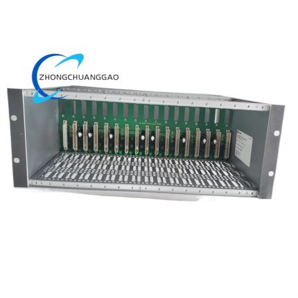
- Hot-swap compatible with all standard and redundant Honeywell C200 control rack architectures
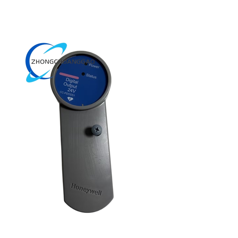
- Individual channel status LED indicators, global power supply LED and module fault warning LED on front panel
- Non-volatile on-board flash memory permanently stores channel configuration, fail-safe and pulse control parameters
Performance Parameters
- Channel Switching Latency: ≤ 1ms turn-on switching time; ≤ 1ms turn-off switching time
- Open-Load Detection Current Threshold: Minimum 5mA DC sink current per channel
- Operational Ambient Temperature Range: 0°C to +60°C operational; -40°C to +85°C long-term storage
- Relative Humidity Operating Tolerance: 5% – 95% non-condensing atmospheric conditions
- Vibration Compliance: 10–150Hz, 1g sinusoidal vibration testing per IEC 60068-2-6 industrial standard
Material Composition
- Main Multilayer PCB: FR-4 high Tg flame retardant fiberglass substrate, full lead-free industrial soldering process
- Terminal Block Housing Material: Reinforced glass-filled PA66 nylon, UL94 V-0 flame retardant safety rating
- Module Mount Frame: Cold rolled steel with black electrostatic epoxy anti-rust and anti-corrosion coating
- Backplane Edge Connector Contacts: Copper alloy with 1.0μm gold plating for long-term stable low-resistance communication
- Internal Electronic Hardware: N-channel MOSFET sinking output drivers, optocoupler isolation chips, TVS surge suppression diodes, self-resetting polyfuse overload protection components
Structural Characteristics
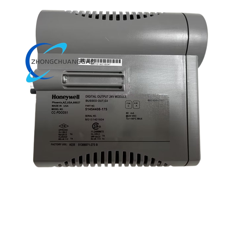
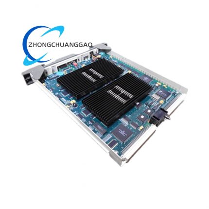
- Standard single-width rack module dimensions: 22.5mm (W) × 130mm (H) × 135mm (D)
- Front panel layout: 16 independent channel status LED indicators, green power status LED, red global module fault LED
- Rear gold-plated edge connector for direct communication with C200 proprietary backplane digital bus
- Removable screw-type terminal block assembly with separate signal load terminals and dedicated cable shielding ground terminals
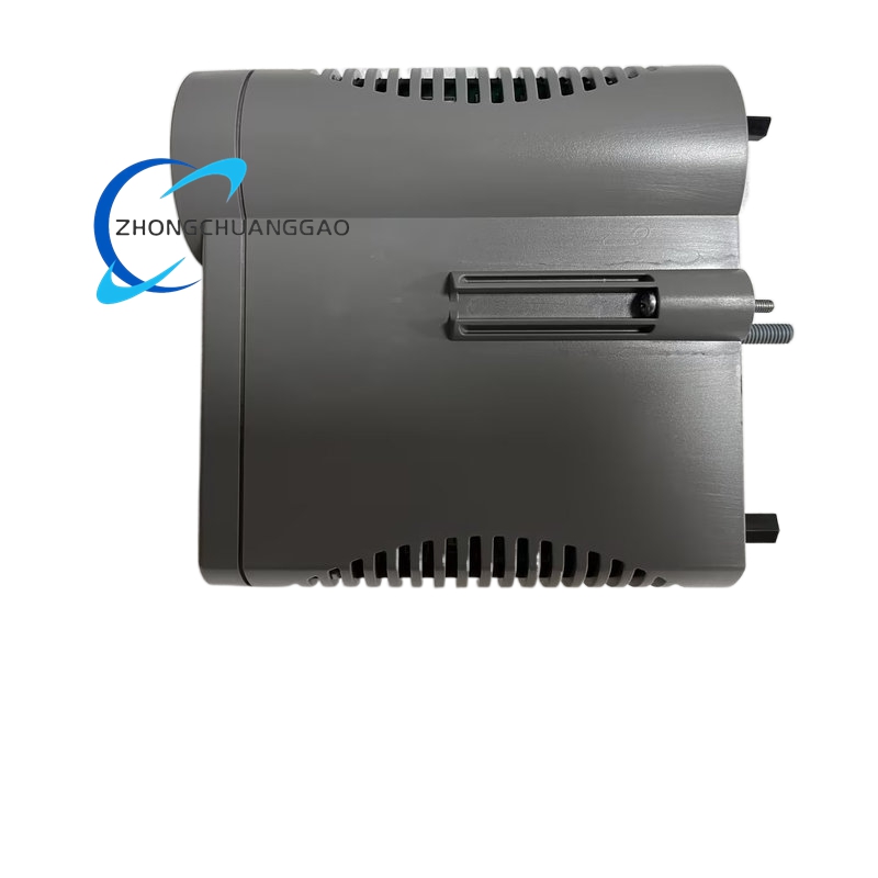
- Dual spring anti-vibration locking latches to secure module firmly inside rack slots under continuous industrial vibration
Working Principle
Binary digital control commands from CC-PCNT01/CC-PCNT02 main controllers are transmitted over the rack backplane bus to the CC-PDOD51 on-board microprocessor. The microprocessor retrieves pre-stored channel configuration and fail-safe parameters from local non-volatile flash memory, then generates isolated drive signals for each channel’s optocoupler isolation circuit. Each optocoupler controls a dedicated low-side N-channel MOSFET sinking driver stage; when activated, the MOSFET creates a return current path to ground for positively sourced external field loads including relay coils, solenoid valves and panel indicator lamps. TVS transient voltage suppression diodes are integrated across each output channel to absorb inductive back-EMF voltage spikes produced during coil de-energization. Every channel circuit incorporates a self-resetting polyfuse electronic fuse; short-circuit or overcurrent conditions trigger immediate channel current cut-off and upload a fault diagnostic flag to the central process controller. In the event of complete rack power loss, pre-programmed fail-safe logic automatically de-energizes all output channels or retains existing load states per user safety settings. All real-time channel energization status and fault codes are cyclically transmitted to the Experion PKS HMI platform for continuous operator monitoring and system troubleshooting.
Advantage Highlights
- Low-side sinking output design matches standard PNP field sensor and relay wiring layouts widely adopted across global industrial automation sites
- Per-channel independent overload isolation ensures single load short-circuit faults do not impact other discrete control output circuits
- Embedded inductive surge suppression eliminates requirement for external parallel freewheeling diodes on solenoid and relay coils
- 16-channel high-density layout minimizes total rack hardware footprint for large-scale discrete control panel assemblies
- Hot-swap maintenance capability avoids full production shutdown during module replacement in fault-tolerant redundant rack configurations
- Built-in open-load detection rapidly identifies disconnected field wiring without time-consuming manual circuit inspection
- Fast 1ms switching latency supports high-speed sequential batch control and automated production line logic sequences
Applicable Industries
General chemical manufacturing discrete control, mining equipment relay interlock systems, food & beverage automated processing lines, HVAC industrial ventilation damper control, municipal water pump relay actuation, light pharmaceutical auxiliary valve control systems
Installation Requirements
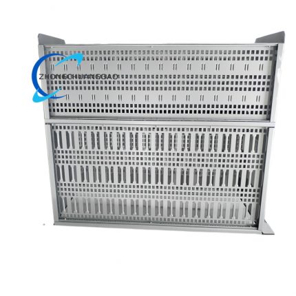
- Installation restricted exclusively to standard Honeywell C200 series control rack with matching original CC backplane chassis
- Maintain minimum 15mm vertical air clearance gap between adjacent modules for forced air cooling circulation
- Cabinet internal cooling airflow minimum performance standard: 0.7 m³/min per complete rack assembly
- All discrete field output wiring must utilize shielded twisted pair cable; cable shielding single-point grounded at cabinet main earth bar
- Terminal block maximum permissible solid copper wire gauge: 14 AWG
- Rack mounting location continuous vibration amplitude limited to less than 0.5mm for long-term stable operation
- Separate low-voltage digital output wiring from high-power AC motor drive and variable frequency control cables with minimum 30cm physical separation distance
Operation & Maintenance Precautions
- Strictly avoid connecting loads exceeding the 0.5A single-channel continuous current rating; sustained overcurrent causes permanent MOSFET driver hardware failure
- Standardized terminal screw tightening torque set at 0.8 N·m to eliminate loose contact thermal resistance and unstable load drive performance
- Verify inductive coil load surge suppression circuit integrity prior to system commissioning to prevent premature module component degradation
- Anti-static wrist strap and anti-static mat mandatory for all module disassembly, wiring modification and physical replacement procedures
- Front panel exterior cleaning restricted to dry anti-static microfiber cloth materials; liquid cleaning agents, alcohol and chemical solvents are fully prohibited
- Confirm redundant standby controller complete online synchronization status before executing hot-swap module maintenance during live production operation
- Spare inventory modules must remain sealed within factory anti-static packaging with desiccant packs to prevent PCB moisture corrosion and circuit performance degradation during long-term shelf storage


























-430x430.jpg)
-430x430.jpg)
-430x430.jpg)
-430x430.jpg)

Reviews
There are no reviews yet.