
Cameron AAP3798102-00130
Product Brief Introduction
Factory OEM long-stroke displacement sensor for Cameron wellhead large-bore gate valves, ball valves, and subsea production tree hydraulic actuators; suffix 00130 designates extended linear measuring stroke configuration. The unit converts full-range actuator mechanical travel into standard 4–20 mA two-wire analog signals for continuous valve position tracking by offshore DCS and subsea control modules.
Cameron AAP3798102-00031
Product Brief Introduction
Original Cameron OEM dedicated displacement sensing component for oil & gas wellhead choke valves, gate valves, and subsea tree actuator assemblies; variant suffix 00031 defines short effective measuring stroke configuration. The unit converts linear actuator mechanical travel displacement into standard 4–20 mA analog signals for DCS and subsea control module (SCM) real-time valve position monitoring, engineered to withstand deep seawater high pressure, salt corrosion, and offshore extreme temperature fluctuation.
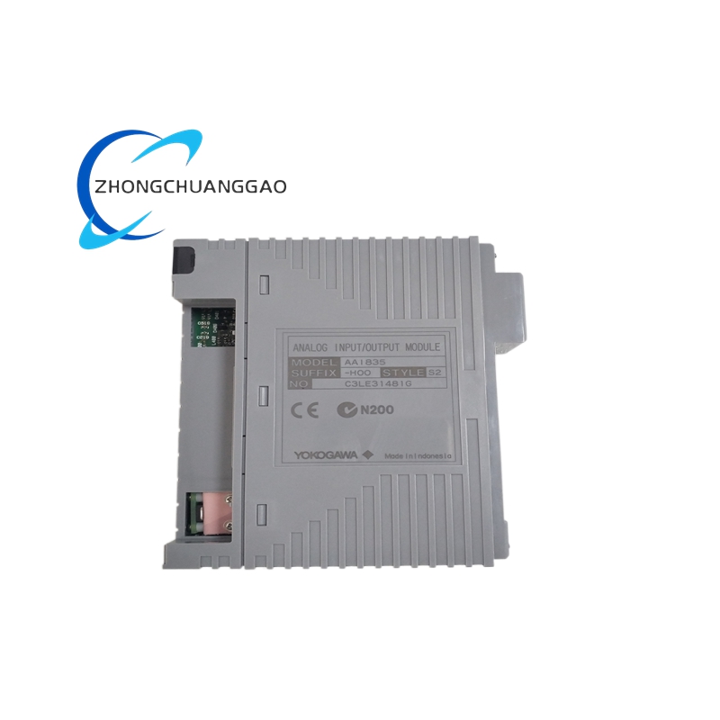
Metso AAI835-H50
Product Brief Introduction
OEM customized dual analog input/output card for Metso Outotec mining and mineral processing DCS platform, original Yokogawa AAI835-H50 hardware core with Metso brand labeling, integrate 4-channel analog signal collection and 4-channel analog control output, HART two-way communication supported, realize simultaneous on-site process parameter measurement and valve/actuator closed-loop control.
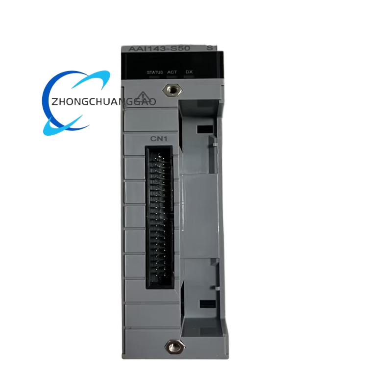
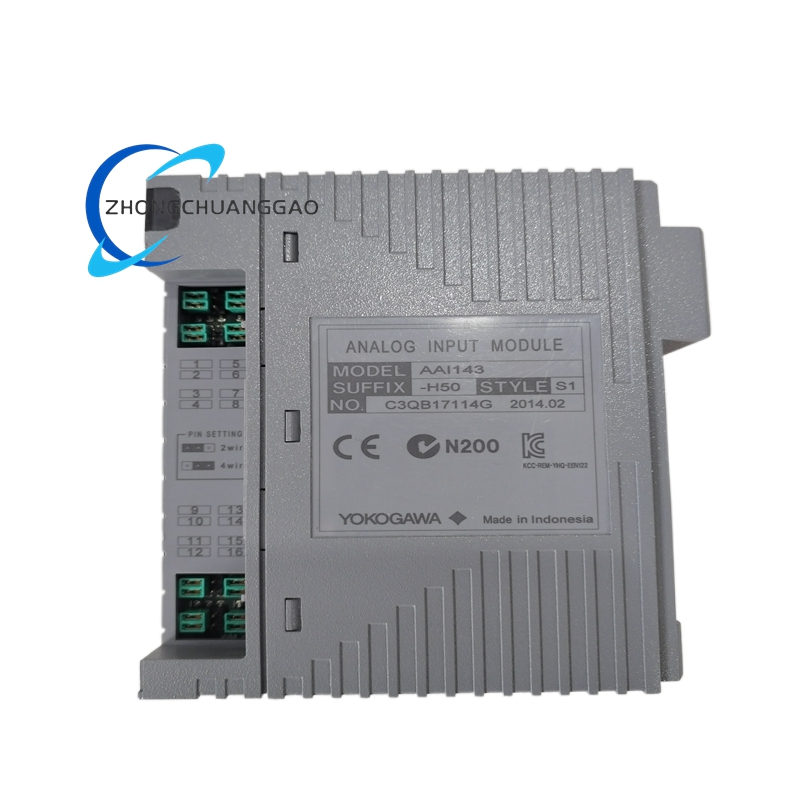
Yokogawa AAI143-S50
Product Brief Introduction
High-density cost-effective analog signal acquisition card of Yokogawa AAI143 series, suffix S50 represents standard basic model without HART digital communication function, only realize high-precision collection of 4–20 mA analog signals from ordinary two-wire transmitters, used for large-scale general process parameter monitoring projects without intelligent instrument remote configuration demand.
Yokogawa AAI143-H50K4A00
Product Brief Introduction
High-density 16-channel analog acquisition card for Yokogawa CENTUM VP DCS system, integrated HART two-way digital communication function, realize real-time measurement of 4–20 mA loop transmitters and remote parameter reading/writing of HART field instruments, suffix H50 represents HART communication enabled non-explosion type, K4A00 matched KS dedicated cable interface adapter ATK4A-00.
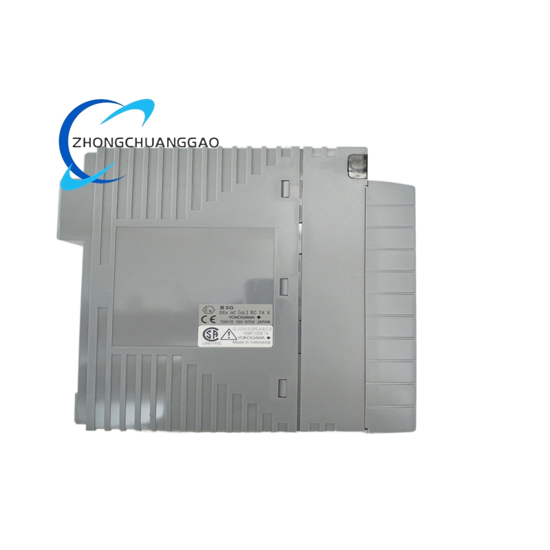
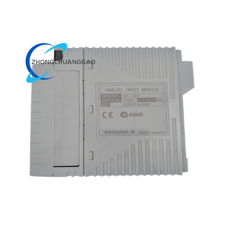
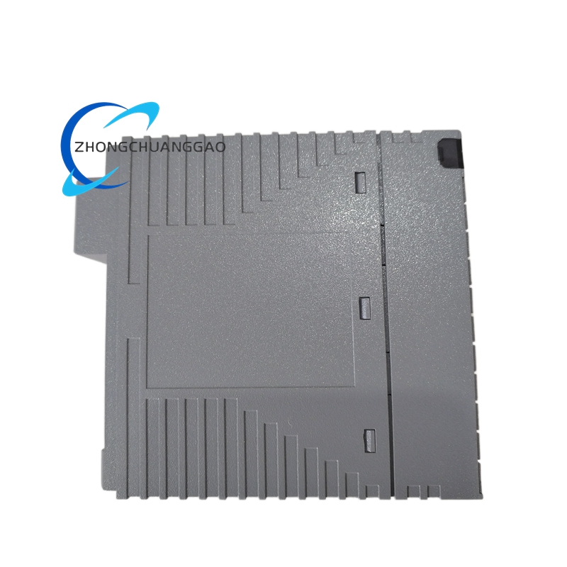
Yokogawa AAI141
Product Brief Introduction
Standard universal signal acquisition card for Yokogawa CENTUM distributed control system, support multi-type analog signal input including voltage, current, thermocouple and RTD resistance temperature signal, built-in cold junction compensation circuit, realize multi-variable process parameter high-precision collection for chemical, petrochemical and power industry DCS cabinets.
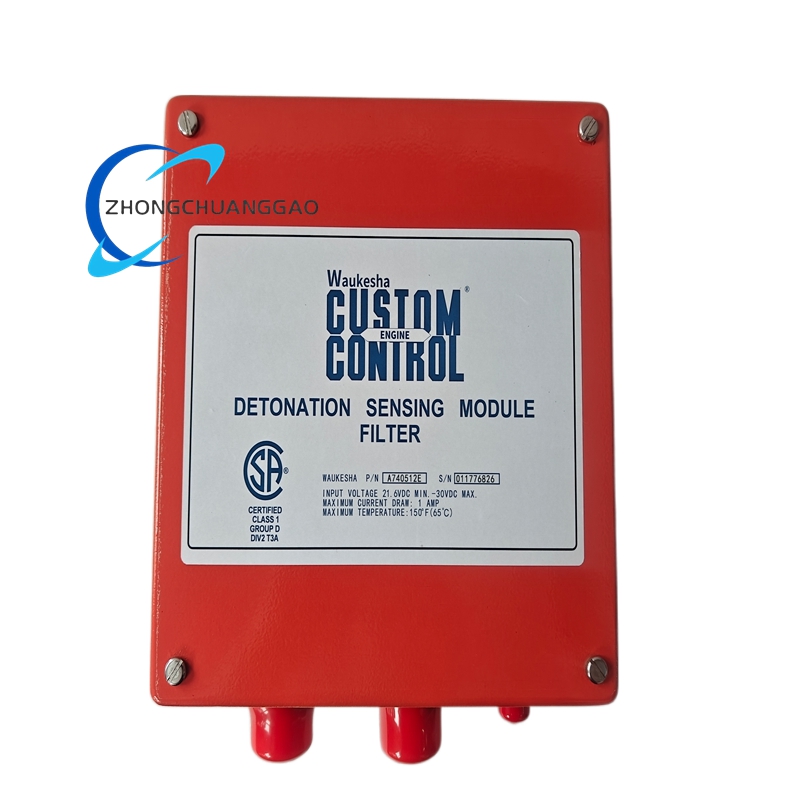
Waukesha A740512E
Product Brief Introduction
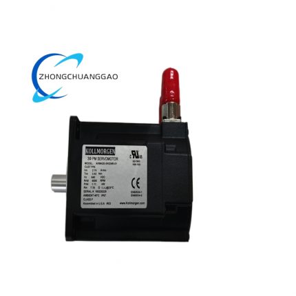
Dedicated ignition drive core component for Waukesha VHP series large-bore gas generator sets, provide high-energy ignition pulse for natural gas, biogas and landfill gas engines, realize closed-loop ignition timing automatic adjustment according to engine speed and load, ensure stable combustion under variable fuel and variable load working conditions.
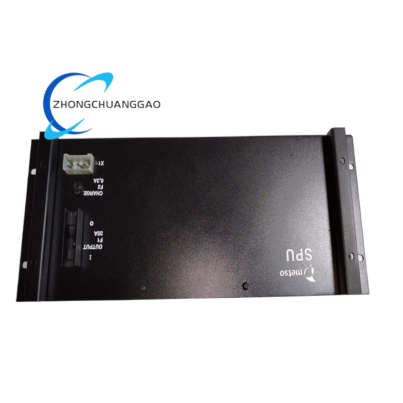
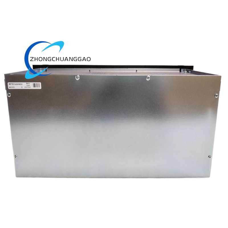
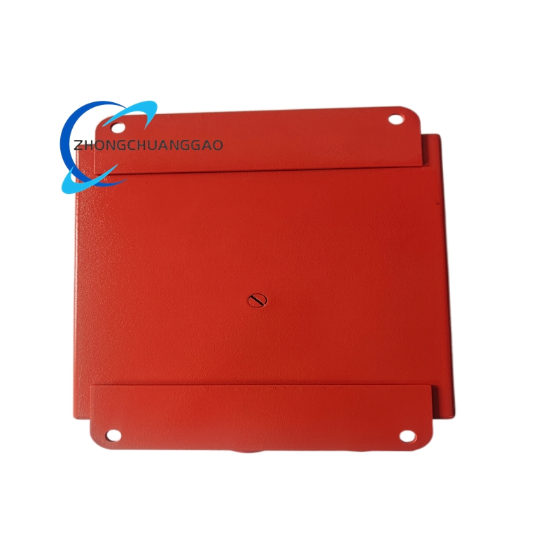
Metso A413331
Product Brief Introduction
Original OEM transmission spare part matched with Metso crusher, feeder and mining automatic adjustment actuator, convert servo motor rotary motion into linear precise displacement, used for ore feeding opening adjustment, crushing gap automatic calibration and screening equipment stroke control, high load impact resistance and long wear service life.
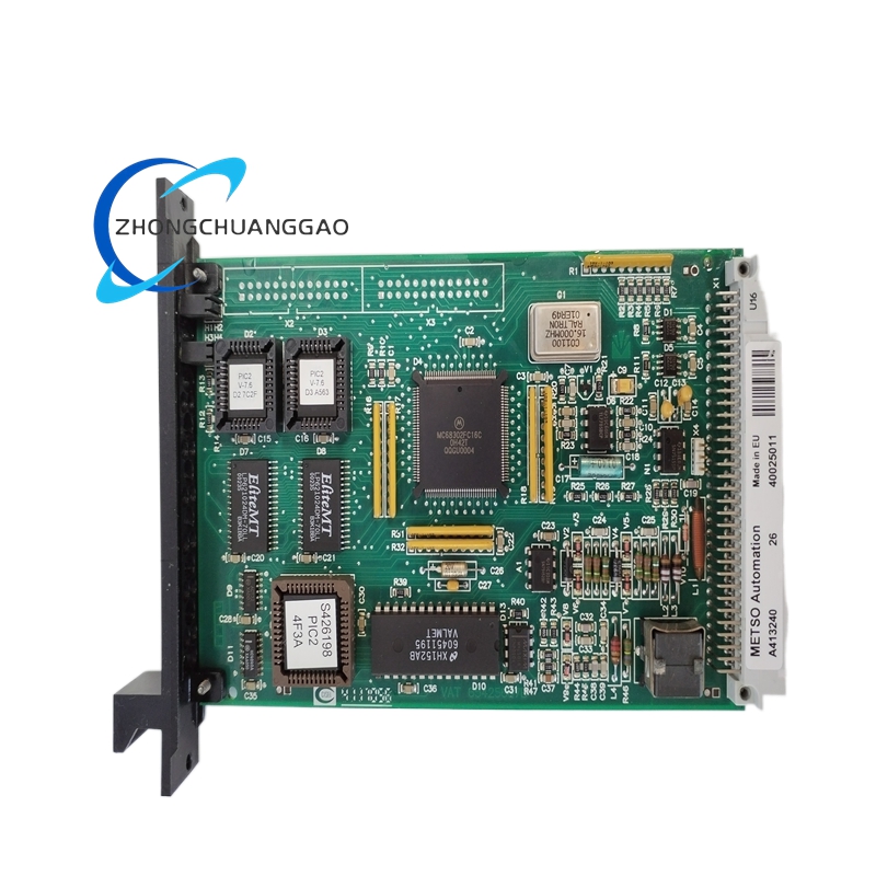
Metso A413240
Product Brief Introduction
Core bus communication bridge card of Metso BIU8 control system, responsible for data exchange between DCS backplane and upper computer HMI, third-party PLC and remote monitoring equipment, realize bidirectional real-time transmission of control commands and measurement data, support multi-protocol adaptive communication.
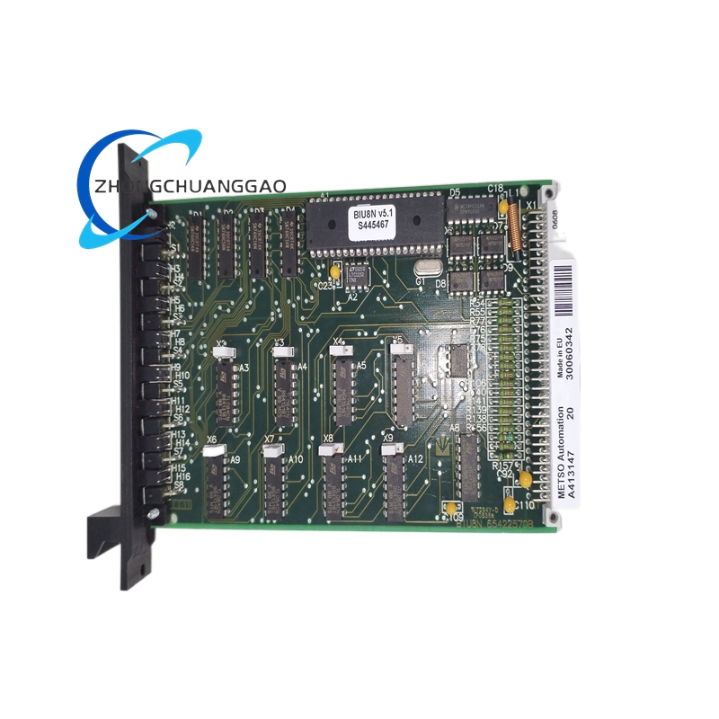
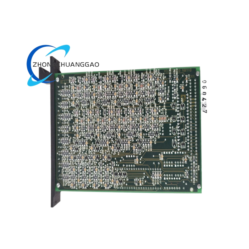
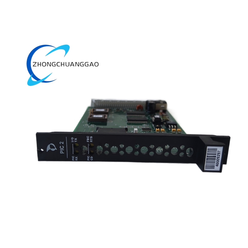
Metso A413147
Product Brief Introduction
Standard field signal acquisition card for Metso Outotec BIU8 distributed control platform, dedicated to collecting analog voltage/current signals from mining, mineral processing and heavy industrial on-site transmitters, realizing high-precision signal conditioning and bus data upload to main controller.
Deltat ACC-68E
Product Brief Introduction
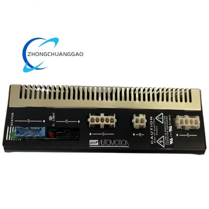
Maximum density encoder feedback expansion card engineered for Delta Tau PMAC, PMAC-2 and PMAC-3 multi-axis motion control platforms. Provides 68 independent differential quadrature encoder input channels for ultra-large scale multi-axis automation systems requiring massive position feedback capacity. Processes digital A/B/Z quadrature signals from servo motors, linear scales, rotary spindles, and auxiliary position transducers entirely via on-board parallel hardware counting circuits without consuming main controller CPU resources.
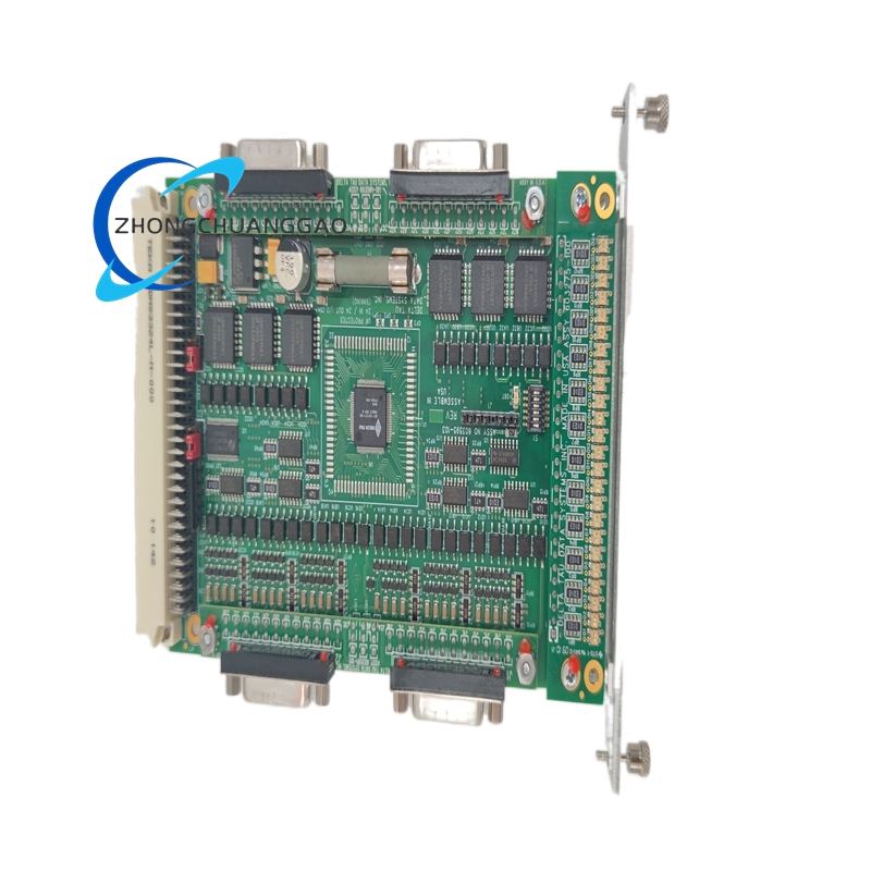
Deltat ACC28B-A-D INTERFACE 24 AXIS
Product Brief Introduction
Rack-mounted standalone signal conversion interface hardware dedicated for large-scale multi-axis PMAC motion control systems. Translates low-level logic motion commands from PMAC mainframe into isolated differential step/direction drive signals for external servo and stepper power amplifiers. Simultaneously collects fault, ready, and limit feedback signals from all 24 drive axes, isolates electrical domains between controller and power drives, and distributes axis enable interlock signals for coordinated machine safety logic.

")


-430x430.jpg)
Reviews
There are no reviews yet.