3. Technical Specifications
- Official Part Number: ZMI‑4104C / 4104C
- Board Mechanical Standard: 6U VME64x Eurocard specification
- Single Board Measurement Axis Quantity: 4 independent measuring channels
- Minimum Acceptable Input Optical Power: 0.07 μW
- Core Position Resolution: 0.15 nm
- Maximum Allowed Measured Object Velocity: ±2.55 m/s
- Measurement Precision at Full Rated Speed (σ): 0.2 nm
- Compatible ZYGO Laser Head Models: 7702, 7714, 7724 series heterodyne laser sources
- Expansion Upper Limit: Multi‑board cascading supports maximum 64 synchronous measuring axes within single VME chassis
- Operating DC Input Voltage: +5 V, +12 V, −12 V standard industrial VME power rail supply
- Operating Ambient Temperature Range: 10 ℃ ~ +40 ℃; Storage Temperature: −45 ℃ ~ +85 ℃
- Relative Humidity Working Range: 10% ~ 85% non‑condensing
- External Communication Interfaces: VME64x parallel bus, auxiliary RS485, EtherCAT real‑time data output port
- Overall Dimension: 233.35 mm (height) × 160 mm (depth) × 20.32 mm (single slot width)
4. Functional Characteristics
- Executes real‑time quadrature demodulation for heterodyne interference optical signals collected from four independent interferometer probes synchronously.
- Embedded full automatic cyclic error correction algorithm to eliminate inherent non‑linear measurement deviation of interferometer optical path.
- Built‑in environmental compensation logic to dynamically correct measurement drift induced by air temperature, atmospheric pressure and ambient humidity fluctuation.
- Implements DynaPhase™ instantaneous high‑speed data sampling and QPSI™ phase acquisition to suppress environmental low‑frequency vibration interference on measurement results.
- Standardized VME bus protocol realizes seamless data interaction with industrial motion controller, PLC and DCS control platform for closed‑loop position feedback control.
- Independent channel fault diagnosis circuit locates open circuit, low optical input power and short‑circuit fault of each measuring axis separately with hardware indicator feedback.
- Supports configurable data output refresh rate ranging from 1 kHz up to 2 MHz to match diversified high‑speed dynamic measurement requirements.
5. Performance Parameters
- Total System Background Noise Floor: ≤0.04 nm RMS under standard laboratory ambient condition
- Channel Crosstalk Interference Value: ≤0.03 nm between any two adjacent measuring axes
- Long‑term Drift Per 24 Continuous Operating Hours: ≤0.12 nm under constant temperature & humidity environment
- Vibration Resistance Standard: Passes 10 Hz ~ 2000 Hz random vibration test with 10 g acceleration rating without measurement deviation or component damage
- Electromagnetic Compatibility Rating: Complies with IEC 61000‑6‑2 industrial immunity standard, anti‑radiation interference ≥10 V/m field strength
- Service Mechanical Cycle Life: ≥100,000 times plug‑in/unplug operations on VME chassis without interface electrical performance degradation
- Refractive Index Correction Accuracy: ±0.1 ppm with external environmental sensor signal access
6. Material Composition
- Base Printed Circuit Board Core: FR‑4 high‑Tg flame retardant substrate with UL94‑V0 fireproof certification, glass fiber reinforced epoxy resin
- Signal & Power Circuit Trace: Electrodeposited oxygen‑free copper with 20 μm minimum copper thickness, surface covered by immersion gold plating (gold thickness ≥0.05 μm)
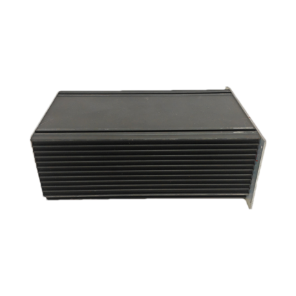
- Front Panel Structural Frame: Die‑cast aluminum alloy with hard anodized anti‑oxidation coating
- VME Gold‑Finger Contact Terminal: High‑elasticity beryllium copper with double‑layer hard gold plating ≥1.2 μm total plating thickness
- Onboard Core Semiconductor Components: Industrial grade silicon monolithic integrated circuits, low‑noise JFET photoelectric preamplifier chips
- Internal Insulation Spacer: Modified PPS high temperature resistant engineering plastic
- External Fixed Fasteners: SUS304 stainless steel anti‑rust screws and positioning pins
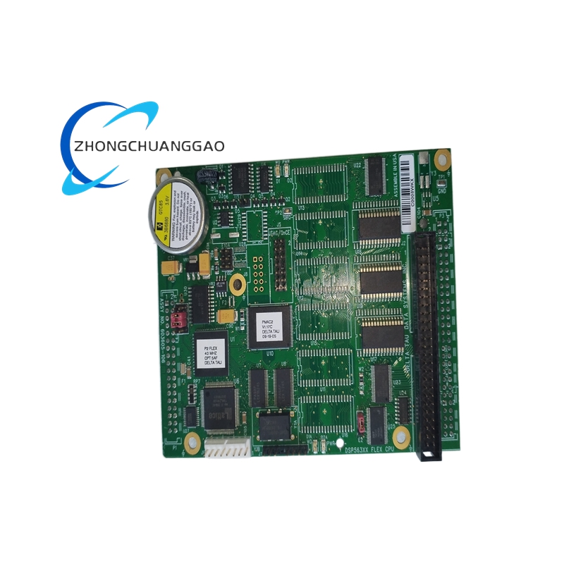
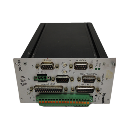
7. Structural Features
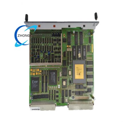
- Standard 6U single‑slot split structure consisting of front aluminum panel and rear main PCB circuit board, fixed by four positioning screws as integral unit.
- Front panel equipped with four independent optical signal input aviation sockets, VME bus gold finger arranged along rear edge of PCB board for chassis plug‑in installation.
- Independent separated regional layout on PCB: analog optical signal preprocessing area, digital FPGA computing area, power supply filtering area to avoid strong/weak electricity mutual interference.
- Embedded multi‑stage LC filtering circuit inside each optical input channel to filter out high‑frequency electromagnetic clutter from external cable transmission.
- Front panel reserved auxiliary communication terminal block for RS485 and environmental parameter sensor wiring access.
- Modular split preamplifier sub‑board design allows single channel partial replacement without whole board disassembly during maintenance.
8. Working Principle
The heterodyne laser beam from matched ZYGO laser head is split into reference optical path and measured optical path inside external interferometer; reflected light from measured target generates interference beat frequency signal after optical path recombination, which is converted into weak electrical signal via photodiode and transmitted to ZMI‑4104C optical input port. Onboard preamplifier circuit amplifies and filters input analog signal, FPGA core chip conducts real‑time phase demodulation to calculate real‑time displacement value from phase difference variation of interference waveform. Built‑in compensation unit receives ambient temperature, pressure, humidity data from external environmental sensor to revise air refractive index error; cyclic correction module offsets optical path inherent non‑linear deviation. Processed digital displacement data is transmitted to upper control system through VME or EtherCAT bus for closed‑loop position control of measured moving platform.
9. Advantage Highlights
- Original ZYGO OEM metrology grade product with full production batch traceability and NIST traceable factory calibration certification, consistent measurement repeatability across all same‑spec units.
- Ultra‑high sub‑nanometer resolution enables precision monitoring of atomic‑level tiny displacement variation unavailable for conventional industrial measurement modules.
- Built‑in full automatic multi‑dimension error correction eliminates extra external compensation equipment purchase cost and reduces system configuration complexity.
- Modular VME cascading architecture realizes flexible axis expansion from 4 axes to 64 axes to satisfy multi‑dimensional multi‑station synchronous measurement demand.
- DynaPhase anti‑vibration sampling technology ensures stable measuring precision under factory workshop vibration environment without additional constant temperature vibration isolation platform investment.
- Strict compliance with EU RoHS environmental directive and US ANSI metrology industry standard, long service life exceeding 10 years under rated operating condition.
10. Applicable Industries
- Semiconductor Lithography & Wafer Manufacturing Industry: Lithography stage positioning calibration, wafer probe station displacement closed‑loop control
- Precision Optics Fabrication Industry: Optical lens polishing equipment real‑time feed displacement monitoring, aspheric component machining dimensional inspection
- Aerospace Precision Component Machining Industry: Aeroengine core part ultra‑precision machining positioning detection, aerospace gyroscope assembly alignment measurement
- New Energy Precision Equipment Industry: Lithium battery high‑precision winding machine, fuel cell core component assembling position control
- Nanotechnology & Scientific Research Field: Laboratory nano‑platform motion calibration, material micro‑deformation dynamic testing
- Ultra‑precision CNC Machine Tool Industry: Ultra‑precision grinding machine feed axis error compensation, coordinate measuring machine (CMM) reference calibration
11. Applicable Model Series
- Host Matching Series: Full ZYGO ZMI™ heterodyne displacement interferometer system product line; compatible with ZYGO 7702,7714,7724 series laser emitter assemblies
- Chassis Matching: Standard 6U VME64x industrial chassis from all mainstream global VME hardware manufacturers
- Upper Control System Matching: EtherCAT servo motion controller, industrial PLC, semiconductor lithography equipment dedicated control platform
12. Installation Requirements
- Complete installation inside constant‑temperature electrical cabinet with ambient vibration acceleration ≤0.1 m/s², keep away from high‑power frequency converter and arc welding equipment with strong electromagnetic radiation source.
- Power off VME chassis main power supply before plugging 4104C into chassis slot, align rear gold finger with VME slot guide rail and insert horizontally until front panel closely fits chassis rack, lock four front panel fixing screws uniformly with 0.9 N·m tightening torque.
- Connect interferometer optical signal cable to front panel input socket straightly without forced skew plugging, fasten socket locking ring to prevent loose contact induced by equipment vibration.
- Wire external environmental temperature, pressure and humidity sensor to reserved auxiliary terminal block following official pin definition specification for automatic refractive index compensation activation.
- Complete whole system power‑on initialization after all wiring finished; execute factory standard calibration procedure with ZYGO certified calibration block before formal measurement startup.
- Reserve minimum 200 mm bending radius for all external signal cables to avoid internal optical fiber or core wire tensile damage during equipment long‑term operation.
13. Usage Precautions
- Strictly prohibit hot plug/unplug operation under powered chassis status to avoid instantaneous surge current damaging onboard precision preamplifier and FPGA chip.
- Prevent liquid, cutting fluid, conductive metal dust from splashing onto board front panel and PCB circuit area; stop equipment operation immediately once liquid contamination occurs and execute full drying maintenance before reuse.
- Do not connect non‑ZYGO third‑party unmatched laser interferometer probes to optical input ports to avoid over‑input optical power burning internal photoelectric receiving components.
- Conduct quarterly routine inspection: check locking tightness of all external sockets, surface dust accumulation on PCB, real‑time zero drift value of each measuring channel, record all inspection data in equipment maintenance log.
- Store spare ZMI‑4104C inside constant‑humidity anti‑static packaging box at 15 ℃~25 ℃ indoor environment, forbid long‑term outdoor storage under direct sunlight and damp environment.
- Keep external signal cables separated from high‑voltage power cables with minimum 15 cm spacing to reduce power frequency electromagnetic interference on measured signal accuracy.

")
")


-430x430.jpg)
Reviews
There are no reviews yet.