2. Product Brief Introduction
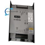
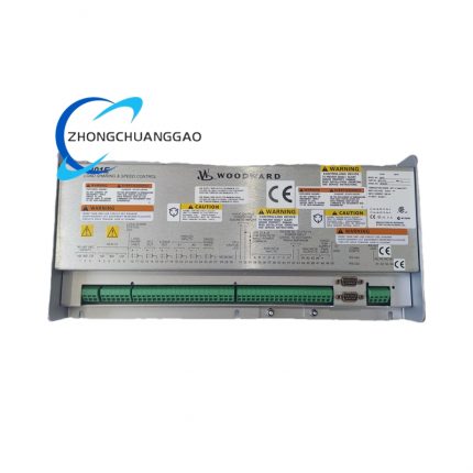
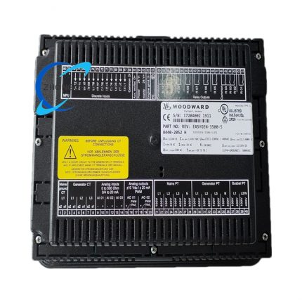
Woodward 9907-838 is a dedicated load distribution control module developed for parallel-connected diesel/gas generating sets. The unit collects three-phase alternating current and PT voltage sampling signals from each paralleled generator, calculates real-time active and reactive power deviation among all gensets via internal microprocessor algorithm, converts computed correction value into standard 0.5~4.5VDC analog adjustment signal and PWM control signal, and transmits output command to engine electronic speed controller to automatically distribute balanced load across paralleled units. The module supports dual control modes of isochronous load sharing and droop load sharing, realizes seamless compatibility between Woodward and Caterpillar brand engine governing systems, and matches Woodward SPM-A automatic synchronizer to complete full-process genset paralleling control. It adopts enclosed metal casing structure for cabinet fixed installation and works steadily under severe vibration and wide-range temperature industrial field environment.
3. Technical Specifications
- Rated DC Working Power Supply: 18VDC~32VDC, nominal rated input 24VDC, built-in reverse power polarity protection circuit
- 3-Phase Current Input Specification: Rated full-load sampling current 3~7ARms AC, transformer secondary current access standard
- 3-Phase PT Voltage Input Range: 95VAC~130VAC single-phase AC input from potential transformer secondary side
- Synchronization Signal Input: Electrical parameter matching Woodward SPM-A series synchronizer dedicated sync signal terminal
- Speed Regulation Control Output: Analog signal output range 0.5VDC~4.5VDC for external speed controller adjustment; standard PWM signal output compatible with Caterpillar digital governor interface
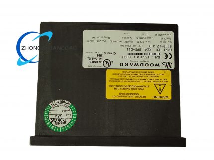
- Overall Outer Dimension: Length 273.6mm × Width 214.1mm × Thickness 59.2mm; net single unit weight 1398g (3.08lb)
- Continuous Rated Operating Ambient Temperature: -40℃ ~ +70℃ (-40℉~+158℉)
- Storage Environmental Temperature: -45℃ ~ +80℃ sealed dry storage condition
- Working Environment Humidity: 5%~95% relative humidity without surface condensation, Pollution Degree 2 per IEC standard
- Anti-Shock Performance: Resist maximum 40G peak impact under 11ms sawtooth pulse shock condition
- Static No-load Power Consumption: Max 4.8W under normal standby state; full-load maximum operating power ≤6.2W
- Wiring Terminal Applicable Wire: AWG22~AWG14 solid/stranded copper control cable
- Formal Certification: UL certified, CE EMC compliant, meets IEC61000-6-2 industrial anti-interference standard
4. Functional Features
- Dual fixed working logic including isochronous zero-droop load sharing and traditional droop load sharing, users switch operation mode via on-board DIP toggle switch without extra software configuration.
- Built-in high-precision three-phase current/voltage sampling circuit, independently collects each genset operating electrical parameter to calculate inter-unit power deviation without external auxiliary calculation equipment.
- Dual-channel output structure: 0.5~4.5VDC analog output for Woodward analog governor and dedicated PWM output channel exclusively for Caterpillar digital speed control system to realize cross-brand equipment matching.
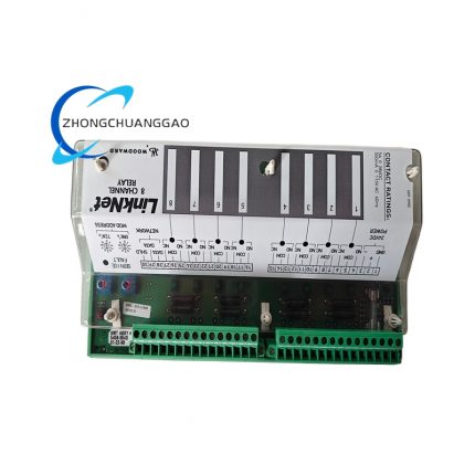
- Independent front-mounted LED indicator set: power indicator, load-sharing operating status indicator, input signal fault indicator separately arranged for real-time running state observation.
- On-board overvoltage, overcurrent and input open-circuit fault detection logic; once sampling circuit abnormal occurs, module locks output automatically and lights corresponding fault LED without interfering other paralleled gensets’ normal operation.
- External potentiometer reserved on panel for manual fine-tuning of load distribution proportional coefficient to adapt different engine fuel response characteristics on site.
- Complete internal surge absorption circuit at all input/output terminals to suppress inductive spike voltage generated from peripheral control equipment switching action.
- Multiple-unit bus cascade connection design; single load-sharing bus supports maximum 16 sets of 9907-838 modules for centralized multi-generator parallel management.
5. Performance Parameters
- Full-load load distribution control precision: ≤±1.5% rated genset active power deviation among all paralleled units under stable grid condition
- Control output response delay: ≤18ms from abnormal load fluctuation detection to effective regulation signal output completion
- Internal microprocessor continuous running MTBF: ≥320000 working hours under rated ambient environment
- Input signal sampling precision error: ≤±0.2% within full 3~7ARms current input range
- Terminal screw repeated fastening service life: ≥2000 times tightening/loosening cycles without thread sliding failure
- Temperature drift coefficient of internal reference voltage: ≤7ppm/℃ across full -40℃~+70℃ operating temperature range
- Droop adjustment linearity error: ≤±0.8% within full preset droop setting range
6. Material Composition
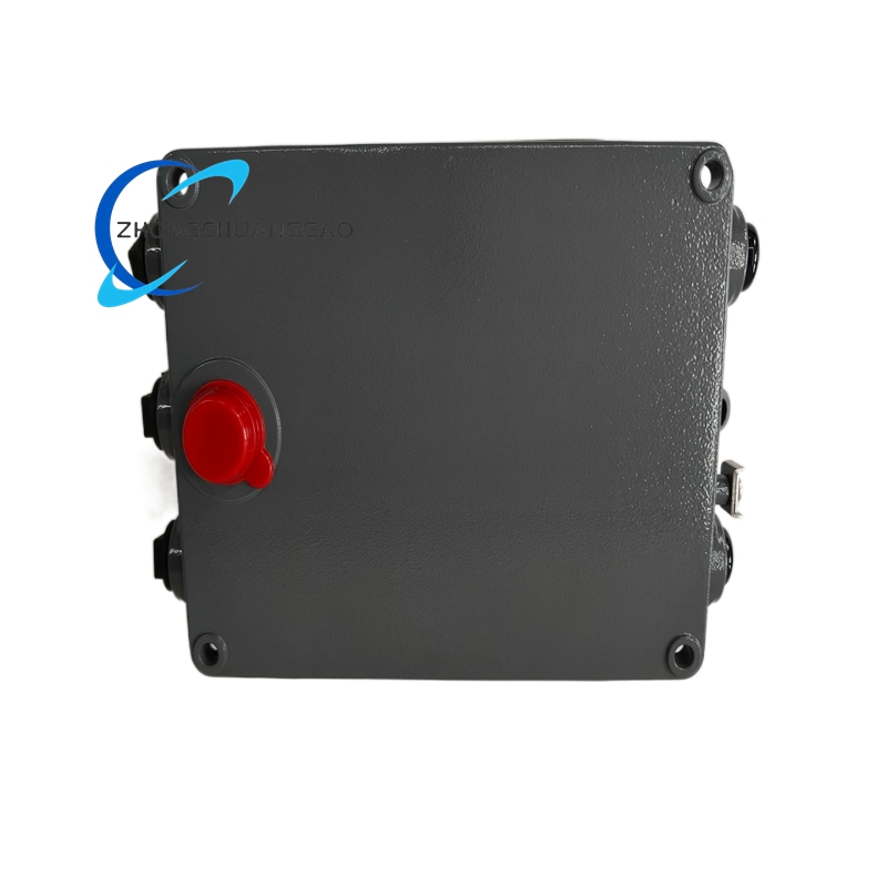
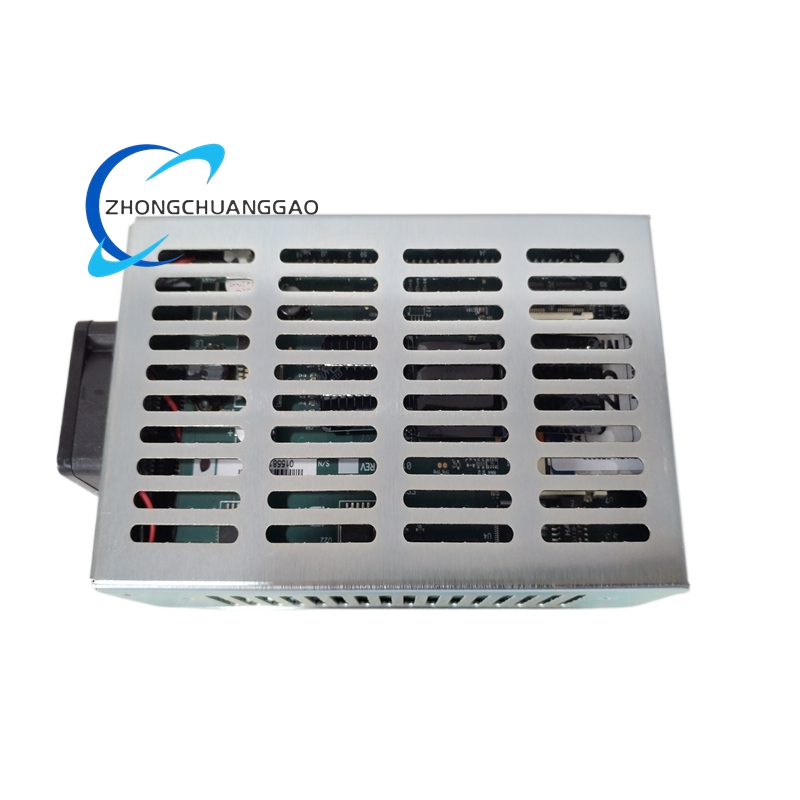
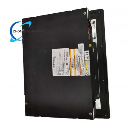
- Outer Equipment Enclosure Shell: Cold rolled steel plate integral stamping forming with matte black epoxy anti-rust spray coating, UL94-V0 flame retardant outer surface protection.
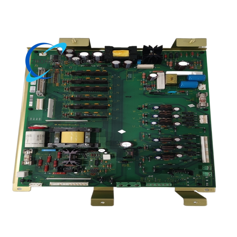
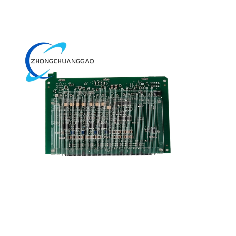
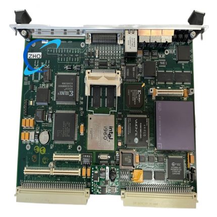
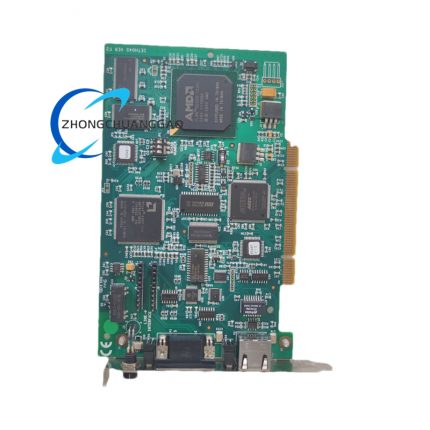
- Main Control PCB Substrate: High Tg FR-4 flame retardant glass fiber circuit board with immersion gold anti-oxidation surface treatment, full SMT patch production technology.
- Wiring Terminal Assembly: Nickel-plated solid brass conductive inserts, zinc alloy anti-loose locking screws and PA66 flame retardant insulating terminal base.
- Internal Sampling Isolation Component: Epoxy sealed miniature current isolation transformer for electrical separation between field high-current input and internal control circuit.
- On-board Core Electronic Parts: Industrial-grade AEC-Q200 passive components, TVS surge suppression diode and high-precision metal film fixed resistor.
- Panel Toggle Switch & Potentiometer: Nickel alloy contact industrial-grade adjustable potentiometer and sealed DIP switch with dustproof rubber outer sleeve.
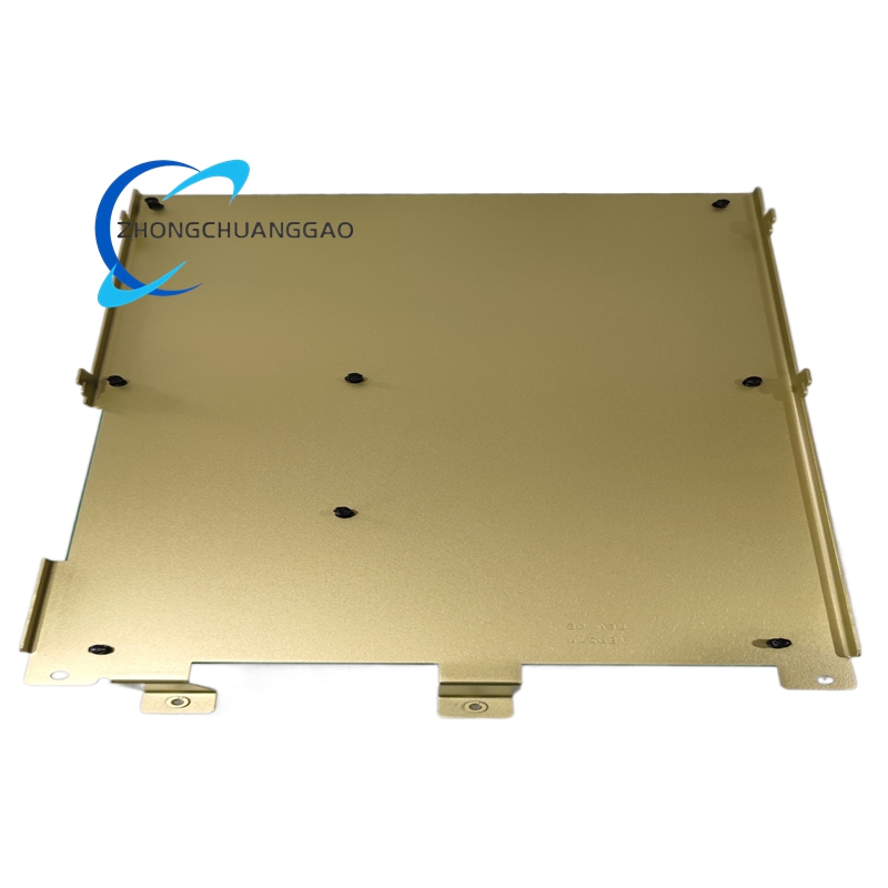
- Internal Fixed Support Hardware: Zinc-plated cold rolled steel stamping bracket and nylon insulation spacing pillars for PCB fixed installation inside casing.
7. Structural Characteristics
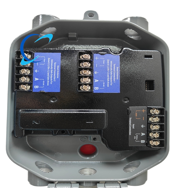
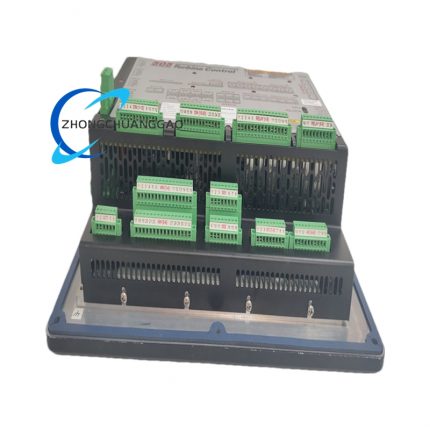
- Rectangular integral enclosed metal casing structure, split internal space into upper sampling signal wiring area, middle main control circuit cavity and lower output terminal area via molded insulation baffle.
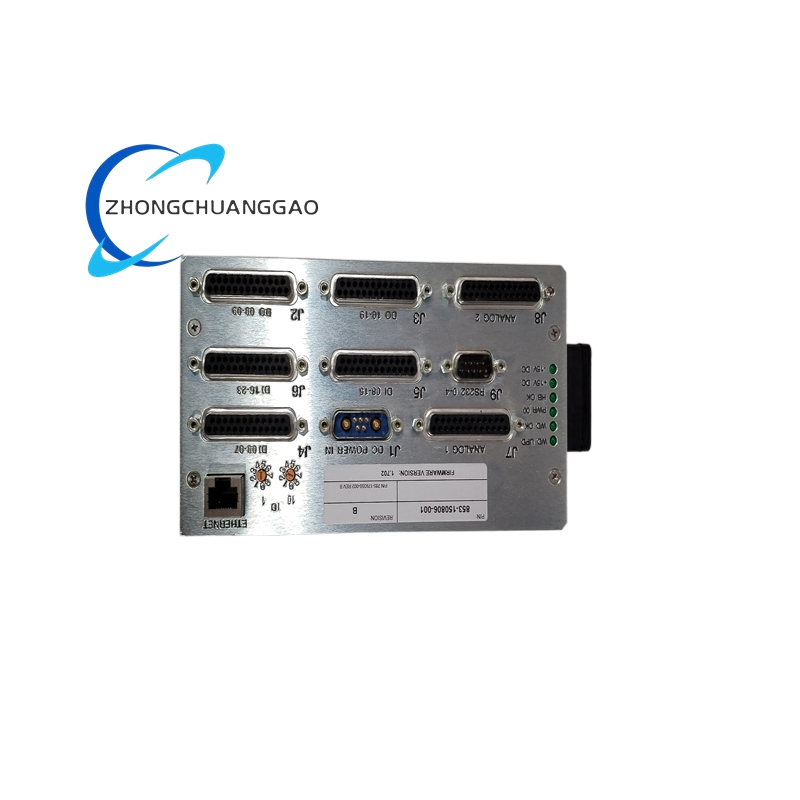
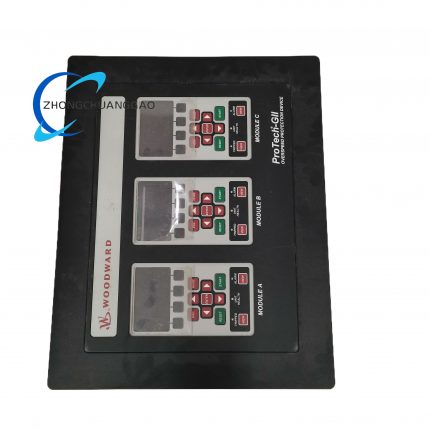
- Front panel layout zoning: left side power and fault LED indicator group, middle manual adjustment potentiometer and mode toggle switch, right side permanent silkscreen terminal definition and model marking.
- Two independent terminal strip layout separated by isolation partition: upper terminal bank for three-phase PT voltage and current sampling input wiring; lower terminal bank for control power supply, sync signal and regulation output wiring.
- Four symmetrical fixed mounting through holes prefabricated on casing left and right side walls for cabinet internal bolt fixed installation without auxiliary DIN rail accessory.
- Top casing reserved strip-shaped natural convection heat dissipation slits to realize passive heat dissipation under long-term full-load continuous working state.
- Backplane integrated wiring limiting rib structure to prevent excessive cable bending damage during field wiring construction.
8. Working Principle
Step1: Field Electrical Signal Collection
Three-phase current transformer and potential transformer transmit real-time generator output current and voltage analog signal into 9907-838 input terminal; internal isolation circuit completes electrical isolation between field power circuit and core control circuit.
Step2: Power Deviation Calculation
Internal microprocessor converts sampled analog electrical parameter into digital value, computes active/reactive power of each paralleled genset, compares unit power with average total power of whole parallel group to obtain load unbalance deviation value.
Step3: Control Algorithm Operation
According to preselected isochronous or droop control mode, core algorithm converts power deviation into corresponding speed adjustment correction quantity.
Step4: Dual Signal Conversion Output
Correction data is split into two forms: 0.5~4.5VDC analog voltage signal for Woodward analog governor and PWM pulse signal exclusively for Caterpillar digital speed controller.
Step5: Engine Fuel Regulation Execution
Received adjustment signal drives engine electronic actuator to increase or reduce fuel supply, change genset output power until all paralleled units reach balanced load distribution state.
Step6: Real-time Status Feedback
Front panel corresponding LED lights up synchronously during normal load-sharing regulation; abnormal input signal triggers fault LED lighting and automatic output locking protection action.
9. Advantage Highlights
- Dual-signal output design achieves universal matching for Woodward analog control and Caterpillar PWM digital control two mainstream genset systems to reduce different model spare part procurement cost.
- Two standard load-sharing working modes satisfy independent grid isochronous parallel and public grid droop parallel two different power station operation requirements with single module.
- Metal sealed casing plus wide -40℃~+70℃ working temperature range adapts outdoor containerized genset cabin and high-temperature engine room severe installation environment.
- Built-in full-channel multi-level fault protection prevents single genset sampling loop short-circuit from causing whole parallel system collapse risk.
- Panel-mounted manual adjustment potentiometer realizes on-site rapid load fine calibration without upper computer configuration software connection.
- High 40G anti-shock structural performance guarantees stable operation under engine long-term vibration working condition of diesel/gas generating set.
- Matching compatibility with Woodward SPM-A synchronizer forms complete set of genset paralleling solution to simplify whole control system layout design.
10. Applicable Industries
- Distributed Power Generation Industry: Natural gas cogeneration unit, biogas genset station, multi-unit diesel emergency power station parallel load control
- Petrochemical Industry: Refinery on-site backup genset, chemical plant process emergency power supply parallel distribution control
- Offshore Oil & Gas Industry: Offshore platform onboard diesel/gas generator group parallel load sharing control
- Mining Industry: Underground coal mine standby power station multi-unit genset parallel power regulation
- Data Center Industry: IDC redundant emergency diesel generator set parallel load automatic distribution
- Marine Vessel Industry: Large ship main/auxiliary generator parallel power balance control
- Construction Engineering Industry: Large engineering project temporary multi-unit mobile genset parallel management
11. Model Series Affiliation
- Parent Core Product Series: Woodward 9907 Series Generator Parallel Load Sharing Control Module Family
- Same Series Sibling Standard Models:
- 9907-836: Single analog output load-sharing module only matching Woodward series analog governors
- 9907-840: Multi-channel bus communication type load-sharing module with RS485 remote monitoring function
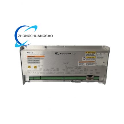
- Compatible Matching Host Equipment: Woodward SPM-A synchronizer, Caterpillar digital speed controller, Woodward 2301/505 series governor, genset PT&CT transformer
12. Installation Requirements
- Mounting Environment Standard: Install inside closed ventilated industrial control cabinet; direct installation in high-corrosion acid/alkali gas confined space is prohibited without additional sealed protective cabinet.
- Fixed Mount Specification: Fix module casing via four prefabricated side mounting holes using grade4 stainless steel bolts with tightening torque controlled at 1.8~2.2N·m to avoid shell deformation from over-tightening.
- Wiring Classification Regulation: Strictly separate sampling input wiring, power supply wiring and control output wiring; power cable and signal cable adopt separate routing to reduce electromagnetic interference.
- Transformer Matching Rule: Field CT secondary current must keep within 3~7ARms rated input range of module; PT output voltage shall not exceed 130VAC maximum input limit.
- Heat Dissipation Clearance Requirement: Reserve minimum 15mm vacant gap above and below installed module for cabinet internal natural convection heat dissipation.
- Pre-power-on Inspection: Verify input voltage, current wiring polarity and output terminal matching load before switching on 24VDC working power supply.
13. Use & Maintenance Precautions
- Strictly forbid live disassembly of module terminal wiring when equipment is powered; hot plugging of sampling input terminal easily leads to internal circuit overvoltage breakdown damage.
- Never access input voltage/current exceeding module rated specification; over-range electrical signal permanently burns internal sampling transformer and core PCB components.
- Quarterly routine maintenance only uses dry lint-free cotton cloth to wipe casing surface dust; alcohol, acetone and corrosive organic solvent direct contact with panel and terminal is forbidden to prevent plastic aging deformation.
- Spare unused modules must be stored inside original factory anti-static shielding bag under 10℃~35℃ dry constant temperature environment; damp open-air long-term storage is prohibited to avoid internal circuit copper pin oxidation failure.
- Critical power station safety parallel loop replacement only allows original genuine Woodward 9907-838 product; refurbished and imitation substitute products cannot access key genset control circuit.
- Avoid high-power inverter and arc welding equipment installed within 60cm distance of control cabinet to prevent strong electromagnetic radiation causing module false load adjustment action.
- Maintenance personnel must wear anti-static wristband before disassembling module to release human body static electricity and avoid electrostatic damage to onboard precision semiconductor chips.


")
")


Reviews
There are no reviews yet.