Product Brief Introduction
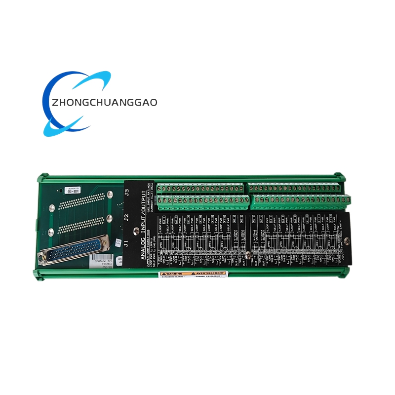
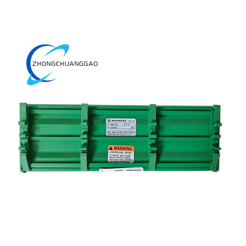
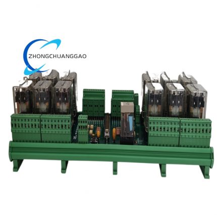
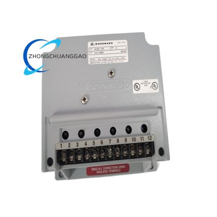
This unit is a dedicated field termination module customized to match Woodward high-density combo analog I/O core control card for prime mover speed governing control system. It serves as intermediate wiring transfer terminal between field site speed pickup sensors, analog transmitters, proportional hydraulic actuators and main control I/O board inside chassis cabinet. The module completes centralized physical wiring sorting, signal distribution and transient surge filtering for all access field signals, strictly matches channel definition of host analog combo control card under simplex control framework. It realizes standardized one-to-one channel mapping of field wiring and internal chassis backplane signal, eliminates scattered loose terminal wiring on cabinet bulkhead, and supports two fixed hardware configuration versions split by analog input signal type: 4–20mA current type edition and 0–5VDC voltage type edition respectively. All internal circuit parameters are factory pre-calibrated without field manual potentiometer adjustment or on-site calibration after replacement.
3. Technical Specifications
- Rated Operating Supply Voltage: 9VDC ~ 30VDC DC input range, nominal rated working voltage 24VDC; built-in full-circuit reverse polarity input protection circuit
- Signal Channel Fixed Configuration Definition:
- 4×Speed Sensor Input Terminals: Compatible with magnetic variable reluctance pickup and eddy current proximity probe input signals
- 8×Universal Analog Input Terminals: Factory fixed either 4–20mA DC current input or 0–5VDC voltage input per module batch specification
- 4×Isolated Analog Output Terminals: Standard 4–20mA DC control signal output channel
- 2×High-current Proportional Actuator Driver Terminals: Supports 4–20mA or 20–160mA direct proportional servo actuator driving output
- Internal Channel Isolation Rating: 500VRMS dielectric isolation between field signal terminal group and internal backplane circuit per single channel
- Analog Conversion Core Resolution: 12-bit fixed hardware AD/DA conversion resolution
- Full Scale Signal Accuracy Index: 0.03% full-scale factory calibrated static accuracy
- Working Ambient Temperature Range: Rated continuous operation: -40°C ~ +85°C; sealed long-term storage temperature: -45°C ~ +90°C
- Allowable Working Relative Humidity: 5%~95% non-condensing environment across full operating temperature span
- Rated Total Static Power Consumption: Max 480mW under full-load all-channel signal access status
- Input Impedance for Speed Channel: Fixed 2000Ω nominal input impedance for frequency pickup signal terminals
- Module Outer Overall Dimension: 220mm (Length) ×125mm (Width) ×32mm (Mounting Thickness)
4. Functional Features
- Fixed one-to-one channel labeling layout; every terminal mark corresponds with host control software channel address definition to eliminate wiring mapping error during field commissioning.
- Integral onboard transient voltage suppression component for all field-connected terminals, automatically absorbing surge spike induced by field actuator coil switch and power grid fluctuation.
- Two independent factory preset hardware variants for analog input, user selects matched module per site transmitter signal specification without internal circuit modification.
- Standard chassis card-guide plug-in structure, directly fixed inside Woodward dedicated control cabinet rack via upper/lower locking screws without extra auxiliary fixing accessories.
- Complete passive signal filtering circuit built in every input channel to restrain industrial field common-mode and differential-mode electromagnetic interference noise.
- No onboard adjustable potentiometer or trimmer component; entire module plug-and-play replacement without post-installation parameter calibration or circuit trimming.
- Dedicated dual-core shield wiring terminal reserved for speed pickup sensor, centralized shielding grounding pin for all field cable shielding layer connection as per Woodward official wiring specification.
- Internal terminal circuit open/short pre-check path reserved for host control board self-diagnosis function, fault signal feeds back to main controller via backplane bus automatically.
5. Performance Parameters
- Single channel signal sampling response delay: ≤350μs from field signal variation to internal backplane signal transmission completion
- Dielectric withstand voltage durability: Every channel sustains continuous 500VRMS AC isolation test for 60 seconds without breakdown or leakage current over 0.5mA
- Mechanical terminal plug cycle lifespan: ≥1500 times wiring terminal screw fastening/unfastening rated service life
- Internal component MTBF value: 215000 hours under standard industrial rated operating environment
- Frequency acceptance range for speed pickup channel: 500Hz~12000Hz selectable via host DIP switch grouping matching field pickup output frequency
- Actuator drive channel linearity error: ≤±0.12% full-scale across full output current range of 20~160mA
- Temperature drift coefficient: ≤18ppm/°C full scale within -40°C~+85°C working temperature span
6. Material Composition
- Main Printed Circuit Board: FR-4 high-temperature resistant flame retardant glass fiber substrate PCB with full immersion tin anti-oxidation surface treatment, SMT+through-hole hybrid component layout process.
- External Terminal Base Housing: UL94-V0 flame retardant PA66 engineering plastic, anti-hydrolysis and anti-oil industrial grade insulation material.
- Wiring Screw Terminals: Nickel-plated solid brass conductive terminal inserts with zinc alloy locking screw components.
- Onboard Passive Protection Components: Automotive-grade TVS transient suppression diode, metal film precision fixed resistors, X7R multilayer ceramic capacitors.
- Cabinet Fixed Front Panel: Cold rolled steel sheet with black electrostatic anti-corrosion coating, vibration-resistant surface passivation treatment.
- Internal Connection Gold-plated Edge Connector: Copper base with 1.0μm hard gold plating for chassis backplane plug connection anti-abrasion.
7. Structural Characteristics
- Integral split structure consisting of front fixed metal panel + rear PCB core assembly, front panel uniformly arranges all categorized terminal groups by input/output function partitioning.
- Standard vertical plug-in design matching Woodward proprietary cabinet internal card guide track, upper and lower panel pre-reserved screw fixing holes for cabinet mechanical locking.
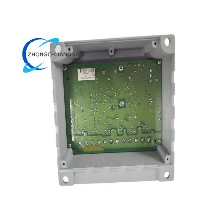
- Internal PCB fixed via six high-temperature plastic positioning pillars inside shell to prevent component displacement caused by equipment runtime mechanical vibration.
- Terminal area compartmentalized by plastic isolation ribs: speed input zone, analog input zone, analog output zone and actuator driver zone physically separated to avoid cross-signal crosstalk.
- Bottom casing pre-opened centralized cable inlet channel with built-in elastic rubber wire clamping strip for external field cable classification and dustproof sealing fixation.
- Front panel printed permanent silkscreen terminal numbering and signal definition mark resistant to high temperature fading and chemical solvent corrosion.
8. Working Principle
Step 1: Field Signal Access Phase
All field sensor, transmitter and actuator wiring access corresponding labeled terminals on 5501-376; external signal enters onboard filtering and surge suppression circuit for preliminary noise elimination and overvoltage protection.
Step 2: Signal Distribution & Isolation Phase
Processed field signal passes through channel isolation circuit to separate field strong interference environment and internal control backplane circuit, blocking common-mode interference from field equipment power loop.
Step3: Backplane Signal Transmission Phase
Standardized filtered signal is transmitted via edge gold finger connector to chassis internal backplane bus, further delivered to matching Woodward high-density combo main I/O control card for AD conversion and digital operation processing.
Step4: Control Output Reverse Transmission Phase
Digital control command converted to analog output signal from main control card flows reversely through backplane into this termination module’s output terminals, then drives field proportional hydraulic actuator or auxiliary peripheral equipment via external wiring.
Step5: Fault Diagnosis Feedback Phase
Internal terminal open-circuit/short-circuit abnormal state captured by built-in detection circuit; fault status is uploaded to main speed governing controller through backplane for real-time fault code display and historical event log storage.
9. Advantage Highlights
- Factory full pre-calibration eliminates on-site manual calibration requirement; same part number direct replacement without system parameter modification to shorten field equipment downtime.
- Channel partition centralized terminal design standardizes cabinet wiring layout, greatly reduces messy scattered loose wiring and subsequent routine maintenance difficulty.
- 500VRMS per-channel isolation structure effectively isolates field harsh industrial electrical interference, improving overall speed control system operation stability.
- Dual fixed input signal configuration version matches mainstream 4–20mA and 0–5V field transmitter universal specifications covering most on-site project design requirements.
- Wide 9~30VDC power supply range adapts industrial site backup battery voltage fluctuation under power failure emergency condition.
- Strict compliance with Woodward original 505 series control system design specification, zero compatibility fault when matched with official original host control equipment.
- Compact chassis plug-in structure saves cabinet internal installation space compared with discrete scattered terminal strip layout scheme.
10. Applicable Industries
- Power Generation Industry: Diesel generator set, natural gas genset, small/medium steam turbine and gas turbine unit speed governing control cabinet configuration
- Petrochemical Industry: Refinery auxiliary prime mover, compressor set and process pump prime mover speed control system matching
- Marine Equipment Industry: Ship main diesel engine, auxiliary generator on-board speed governing control cabinet field signal termination
- Waste-to-energy Power Plant: Biomass combustion turbine and reciprocating engine automation control system
- Heavy Machinery Industry: Large mining diesel driven equipment, stationary industrial reciprocating engine control system
- Oil & Gas Upstream Industry: Wellsite gas engine driven compressor and pumping unit governing control assembly
11. Model Series Affiliation
- Parent Product Series: Woodward 505 Series High Density Combo Analog I/O Termination Module Family
- Sibling specification variants inside same series:
- 5501-375: Full digital signal field termination matching module for discrete digital I/O control card
- 5501-377: Dual redundant backup analog termination module for duplex redundant governing control system
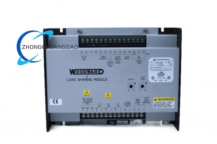
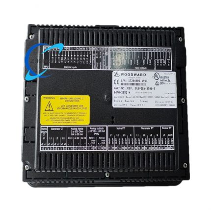
- Compatible matching host control equipment: Woodward 505 Digital Speed Controller, Woodward 505LS Advanced Load Sharing Governor mainframe and corresponding combo core I/O main card
12. Installation Requirements
- Mounting Environment Standard: Install inside closed ventilated industrial control cabinet; prohibited installation inside high-humidity, corrosive gas accumulation or explosive classified hazardous space.
- Chassis Plug-in Rule: Insert module along dedicated cabinet internal plastic card guide track until edge connector fully engages backplane socket, fasten upper and lower front panel fixing screws with cabinet rack to eliminate vibration gap.
- External Wiring Specification: Speed pickup sensor wiring must adopt single-end shielded twisted-pair cable with shielding layer concentrated connected to module reserved grounding terminal; analog signal cable uses 0.75~1.5mm² shielded control wire, actuator high-current drive wiring adopts 1.5~2.5mm² insulated copper cable.
- Heat Dissipation Clearance Requirement: Minimum 12mm vacant space reserved above and below module inside cabinet for natural convection heat dissipation; no high-power heating component attached within 20mm range of module housing.
- Cabinet Grounding Specification: Module dedicated shielding ground terminal connects to control cabinet PE protective earth bus with independent grounding wire, separated from high voltage power distribution ground loop.
- Pre-installation Confirmation: Verify module analog input version (4–20mA or 0–5V) matches field transmitter signal specification before chassis insertion installation.
13. Use & Maintenance Precautions
- Strictly prohibit hot plugging/unplugging module under powered chassis backplane status; live plug operation causes instantaneous surge voltage to damage internal PCB components permanently.
- Never access voltage/current signal exceeding module rated terminal specification into any input/output terminals; over-range signal input leads to internal channel circuit breakdown.
- All field wiring disassembly or modification operation must be completed after cutting off cabinet total 24VDC control power supply to avoid accidental short-circuit triggering main controller fault shutdown.
- Quarterly routine maintenance only uses dry lint-free cloth to wipe front panel terminal dust; organic solvent, alcohol or liquid detergent cleaning is forbidden to contact PCB and plastic terminal base.
- Spare unused modules must be stored inside sealed anti-static shielding bag under 10°C~35°C dry constant temperature environment; open-air damp or high-temperature long-term storage is prohibited.
- Damaged field replacement only permits original Woodward factory certified genuine 5501-376 module; third-party refurbished or non-original substitute modules cannot access formal certified speed governing control system.
- Avoid high-frequency inverter, arc welding equipment installed within 40cm distance of control cabinet housing where module is mounted to prevent strong electromagnetic radiation inducing abnormal signal drift.




























Reviews
There are no reviews yet.