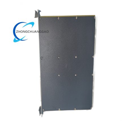
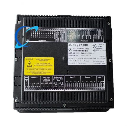
Woodward 9907‑1200

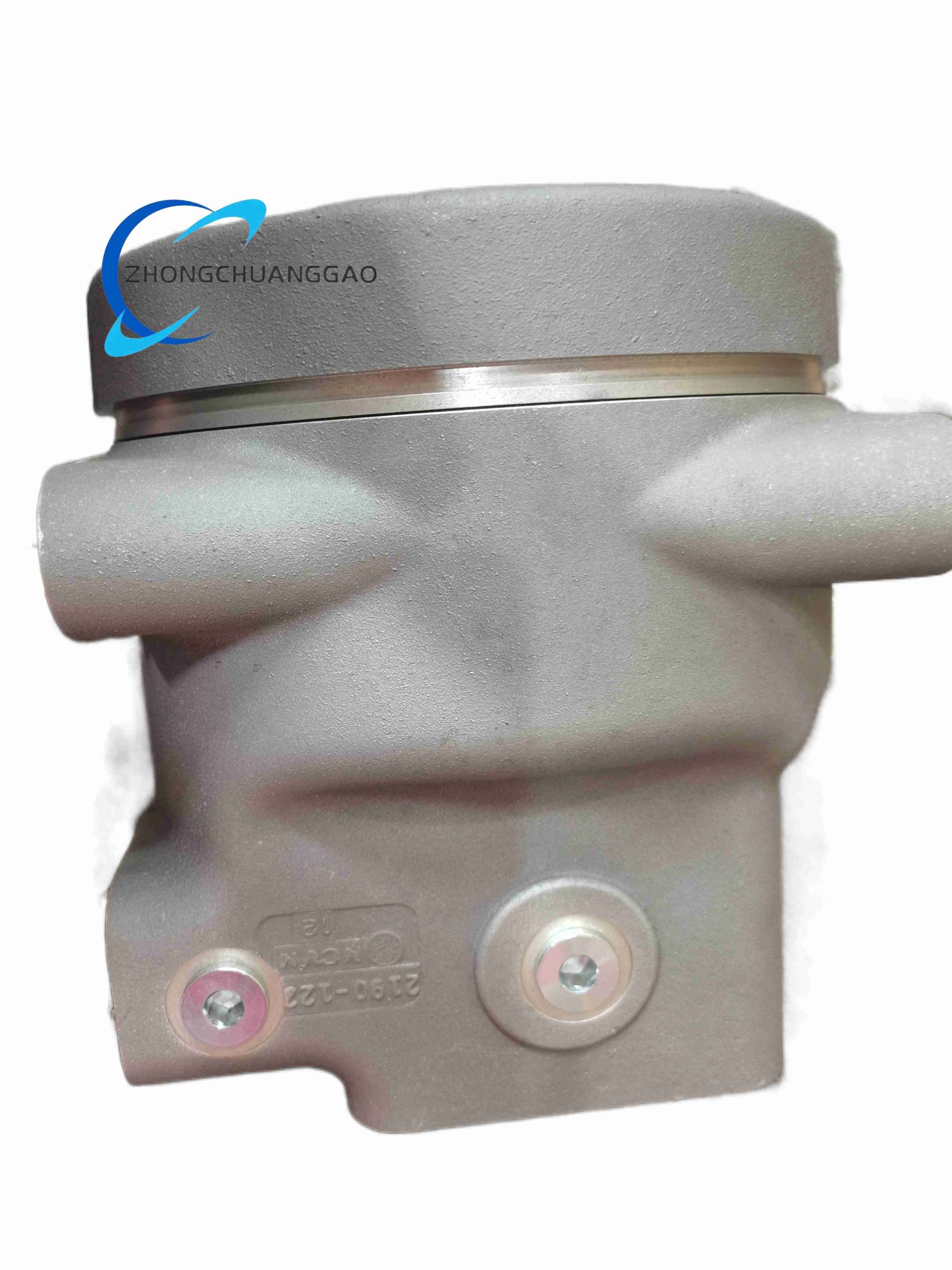
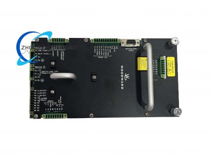
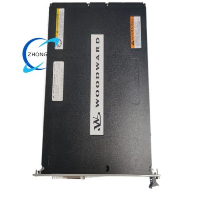
Product Name: CPC‑II Current‑to‑Pressure Electro‑Hydraulic Converter, Model 9907‑1200
Product Introduction: Woodward 9907‑1200 CPC‑II is high‑precision electro‑hydraulic conversion component for steam‑turbine governor‑valve control. It converts 4‑20 mA DC control signal input into proportional hydraulic pressure output to drive single‑acting steam‑turbine control valve. It integrates manual stroke adjustment, valve‑flow linearization compensation and silt‑buster self‑cleaning function, adapting to oil‑contaminated harsh turbine‑system environment.
Category:
Description
Technical Specifications:

Input signal: 4‑20 mA DC analog control current

Output: Proportional hydraulic pressure for single‑acting turbine valve actuation

Linearization table: 11‑point valve‑flow compensation table

Operating temperature range: ‑40 °C to +85 °C

Protection class: IP66

Working medium: Turbine control hydraulic oil

Manual adjustment: Local manual‑stroke screw and remote service‑tool adjustment support

Functional Features:

Converts electrical control current signal to proportional hydraulic pressure output for turbine valve positioning.

Eleven‑point linearization table compensates non‑linear characteristic of steam‑valve flow curve.

Silt‑buster self‑cleaning routine periodically flushes internal flow‑path to reduce silt deposition risk.

Local manual‑stroke screw allows on‑site manual output‑pressure adjustment with safety interlock preventing mis‑operation.

Supports remote configuration and calibration via special service tool.

Failsafe mechanism guarantees safe state under abnormal input‑signal condition.

Application Scenarios:

Steam‑turbine speed‑governing system, power‑plant turbine‑generator unit control loop, industrial steam‑turbine prime‑mover valve‑position control.

Performance Parameters:

Input signal resolution: 12‑bit effective resolution for 4‑20 mA input range.

Conversion response time: Less than 150 ms full‑scale step response.

Material Composition:

Main housing: High‑strength corrosion‑resistant cast‑aluminum alloy housing.

Internal flow‑path: Hardened alloy steel valve spool and valve‑sleeve components with anti‑wear surface treatment.

Electrical‑part shell: Sealed metal electrical junction box.

Sealing components: Oil‑resistant fluororubber sealing rings for hydraulic‑circuit sealing.

Structural Features:

Integrated compact electro‑hydraulic combined structure.

External manual‑stroke adjusting screw with protective cover.

Hydraulic‑oil inlet‑outlet threaded ports with self‑cleaning flow‑path design.

Fully‑sealed electrical junction box with cable‑gland for field‑cable entry.

Mounting lug holes for fixed installation on turbine cabinet or valve‑bank assembly.

Working Principle:

4‑20 mA DC analog control signal enters internal electromagnetic drive unit, which drives precision hydraulic spool‑valve assembly. The spool‑valve adjusts hydraulic‑oil flow‑rate to generate output hydraulic pressure proportional to input current value. Output hydraulic pressure acts on single‑acting steam‑turbine valve actuator to realize valve‑opening adjustment. Built‑in linearization data corrects deviation between input signal and actual valve flow. Silt‑buster program periodically moves internal spool to flush sediment inside flow‑passage.

Installation Requirements:

Fix unit on vibration‑damped mounting support near turbine hydraulic‑valve group.

Connect hydraulic‑oil pipeline according to port marking, ensure pipeline cleanliness before connection.

Use shielded twisted‑pair cable for 4‑20 mA signal wiring; ground cable shield at single end.

Keep electrical junction box away from high‑temperature steam pipeline.

Reserve operation space for local manual‑stroke screw adjustment.

Complete all hydraulic‑pipeline and electrical‑cable connection under system depressurized and power‑off condition.

Usage Notes:

Ensure control‑oil cleanliness meets turbine‑system standard, reduce solid‑particle contamination.

Do not remove protective cover of manual‑stroke screw under normal operating status.

Perform configuration of 11‑point linearization parameters according to actual steam‑valve flow characteristic curve.

Execute silt‑buster function configuration according to oil‑contamination degree.

Check hydraulic‑sealing parts regularly for oil‑leakage phenomenon.

Reviews (0)

Reviews

There are no reviews yet.

Be the first to review “Woodward 9907‑1200”

Your email address will not be published. Required fields are marked *

Shipping and Delivery

MAECENAS IACULIS

Vestibulum curae torquent diam diam commodo parturient penatibus nunc dui adipiscing convallis bulum parturient suspendisse parturient a.Parturient in parturient scelerisque nibh lectus quam a natoque adipiscing a vestibulum hendrerit et pharetra fames nunc natoque dui.

ADIPISCING CONVALLIS BULUM

  • Vestibulum penatibus nunc dui adipiscing convallis bulum parturient suspendisse.
  • Abitur parturient praesent lectus quam a natoque adipiscing a vestibulum hendre.
  • Diam parturient dictumst parturient scelerisque nibh lectus.

Scelerisque adipiscing bibendum sem vestibulum et in a a a purus lectus faucibus lobortis tincidunt purus lectus nisl class eros.Condimentum a et ullamcorper dictumst mus et tristique elementum nam inceptos hac parturient scelerisque vestibulum amet elit ut volutpat.