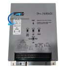
3. Technical Specifications
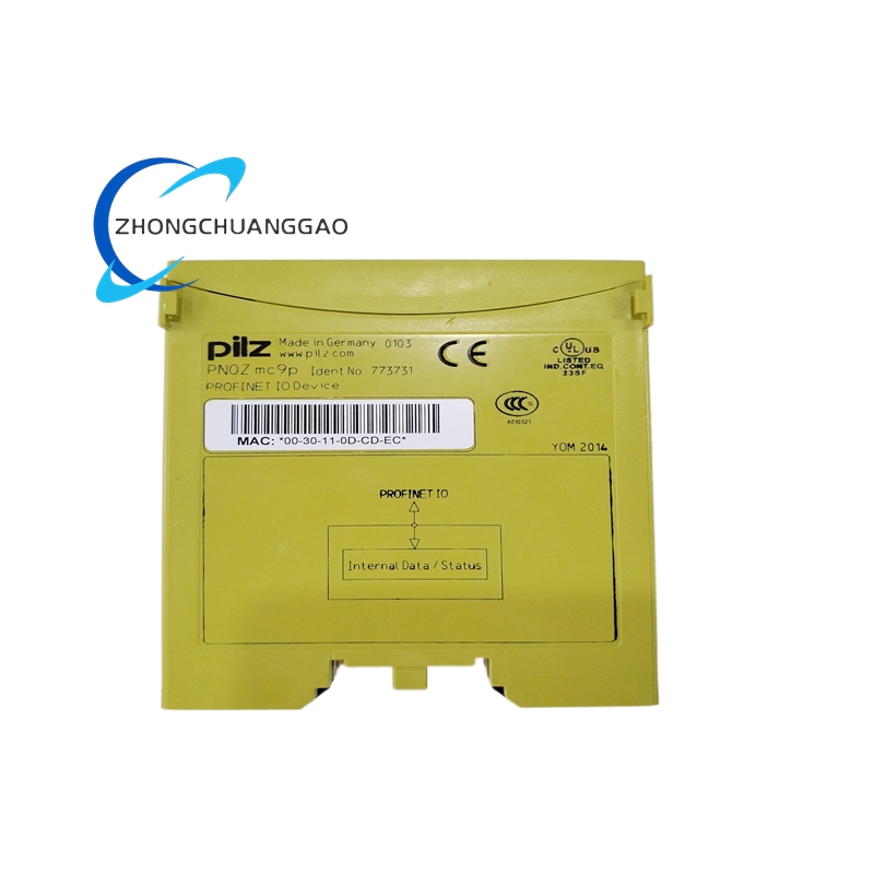
- Official Part Number: 9907-029, standard hardware Revision E fixed version
- Rated Working Input Power: Dual configurable AC power input, nominal 115VAC/230VAC, valid operating voltage range 90VAC~253VAC, typical static power consumption 5W
- Applicable Rated Grid Frequency: Fixed adaptive range 45Hz~65Hz, standard factory preset for 50Hz/60Hz two global mainstream power frequency grades
- MPU Speed Signal Receiving Range: Magnetic pickup input frequency scope 1Hz~11450Hz, compatible with all conventional engine MPU speed sensor output specification
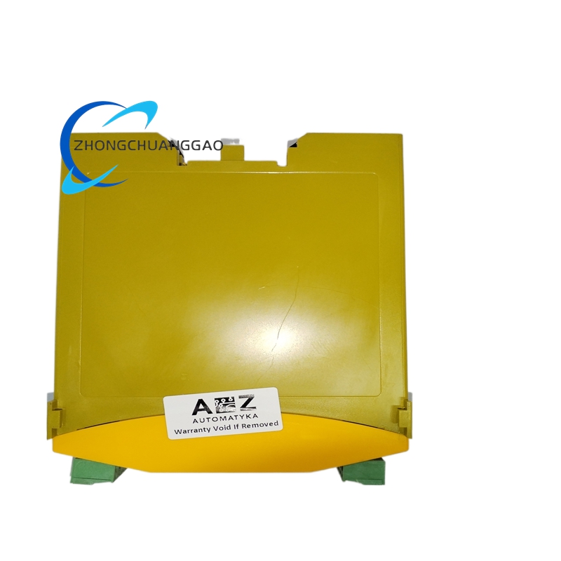
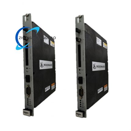
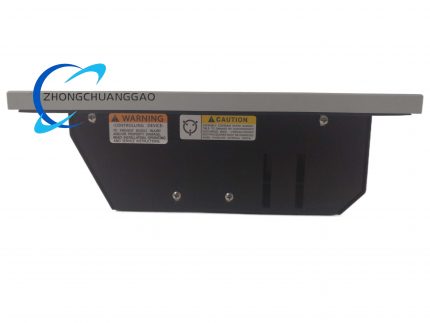
- Physical Overall Dimension: Width 315mm × Height 210mm × Depth 47mm; single unit net weight 1760g
- Continuous Rated Operating Ambient Temperature: Valid long-term working range -40℃ ~ +70℃; restricted high-temperature continuous full-load upper limit +60℃
- Non-operational Storage Temperature Range: -45℃ ~ +85℃, no condensation allowed in sealed storage environment
- Valid Working Ambient Humidity: 5%~95% relative humidity with zero internal cabinet dew condensation
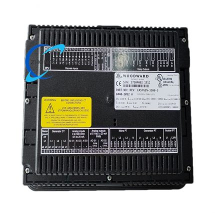
- Two Types Control Output Impedance: High-impedance output for 2301 series governor matching; low-impedance output dedicated for 2301A/EPG/2500 series actuator drive matching
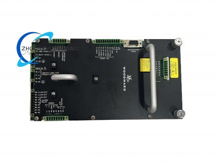
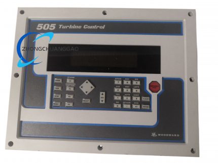
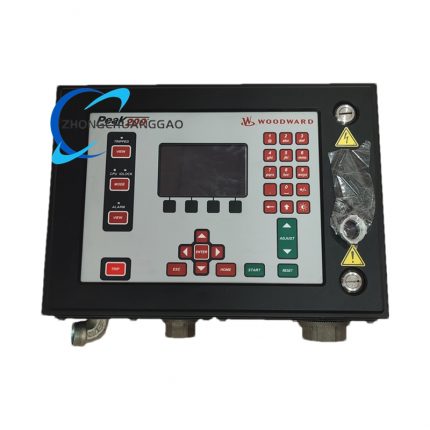
- Front Panel Adjustment Structure: 6 groups of independent precision adjustable potentiometers for synchronization speed gain, voltage bias, phase locking threshold parameter setting
- Enclosure Protection Grade: Front panel IP30 anti-dust standard for indoor cabinet fixed installation
4. Functional Characteristics
- Three independent closed-loop regulation functions: frequency bias adjustment for engine speed trimming, voltage bias adjustment for generator AVR output modification, phase angle pre-alignment for closing margin control, three loops work synchronously during whole synchronization process.
- Built-in anti-hunting damping circuit suppresses repeated speed fluctuation caused by governor over-adjustment in low-inertia diesel/gas engine unit condition.
- Automatic closing permission logic outputs dry contact closing signal only after frequency, voltage, phase three items all fall within preset allowable threshold range to prevent out-of-step paralleling fault.
- Dual output impedance switching design realizes one module compatible with full range Woodward 2301/2301A/EPG mainstream governor models without external signal conversion adapter.
- Built-in input surge suppression circuit withstands instantaneous 2.5kV surge pulse interference from field PT secondary wiring to avoid internal circuit breakdown.
- Full analog hardwired control structure operates normally without auxiliary communication program, adapts harsh field environment without upper computer parameter downloading dependence.
- Adjustable synchronization capture speed range shortens paralleling waiting time under heavy-load grid fluctuation working condition.
5. Performance Parameters
- Rated phase matching closing precision: maximum allowable closing phase difference ≤±10° between generator and busbar at rated frequency condition
- Steady-state frequency tracking control precision: frequency deviation correction control accuracy ≤±0.05Hz full scale rated frequency
- Voltage matching control precision: generator-bus voltage deviation adjustment accuracy ≤±1% rated nominal voltage
- Control signal response speed: full closed-loop regulation response time ≤20ms after deviation signal access to input terminal
- Long-term continuous running parameter drift: potentiometer set value drift ≤0.03%FS after uninterrupted 8760-hour full-load continuous operation at standard 25℃ ambient
- Mechanical anti-vibration performance: passes 10Hz~150Hz 5G random vibration durability test without internal component desoldering and parameter drift
- Certified rated MTBF index: minimum verified service life 295000 continuous operating hours under standard rated industrial operating environment
- EMC anti-interference performance: no control logic disorder or wrong closing output under 10V/m radiated RF field complying with IEC61000-6-2 industrial standard
6. Material Composition
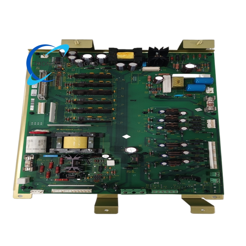
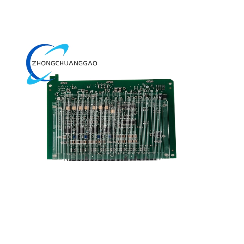
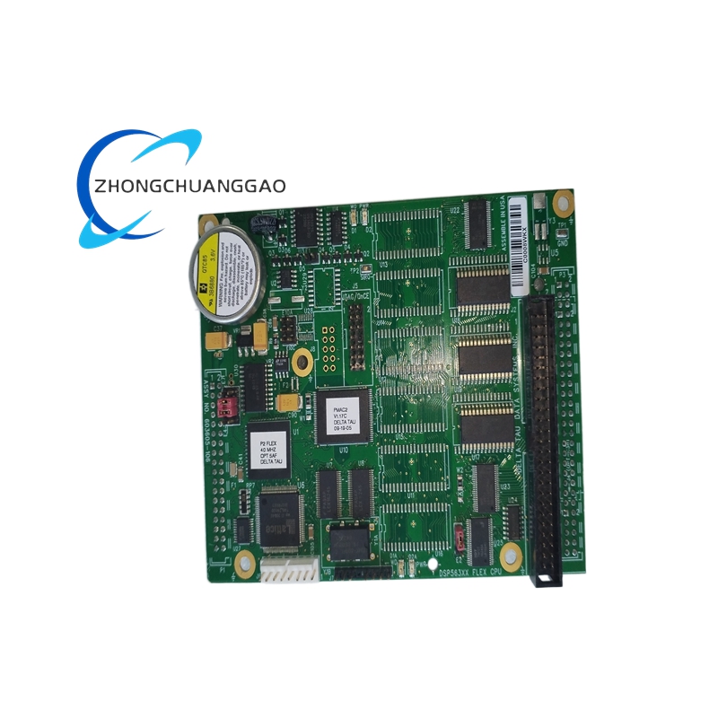
- Core Main Control PCB Substrate: UL94-V0 flame retardant high-Tg FR4 epoxy glass fiber copper-clad board with whole-board factory conformal insulating coating against damp corrosion
- Precision Analog Core Components: low-temperature drift metal film fixed resistors, NPO temperature-stable chip capacitors, industrial-grade operational amplifier chips, sealed glass-passivated diode components
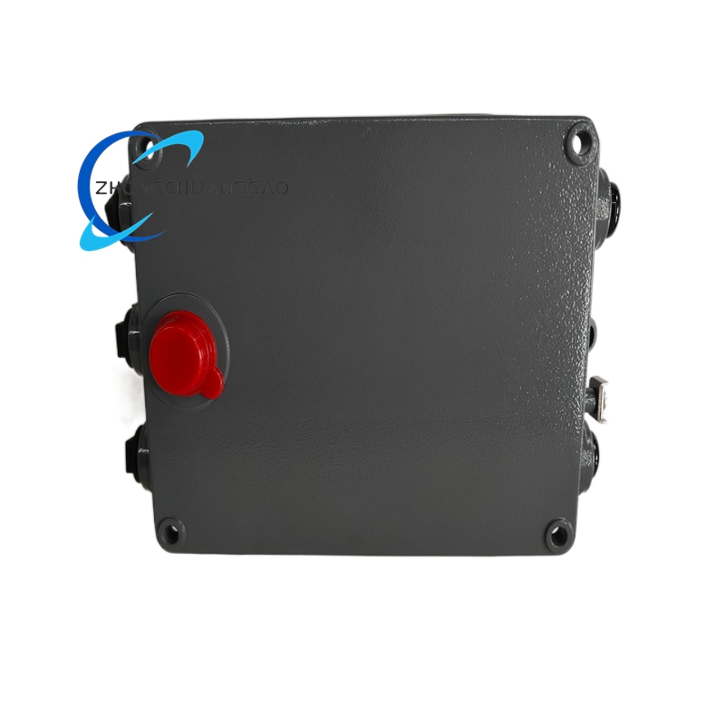
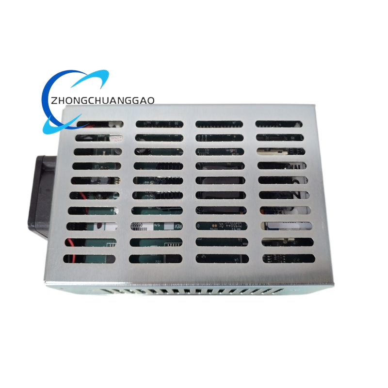
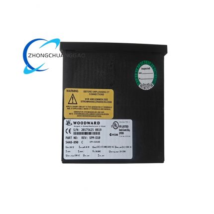
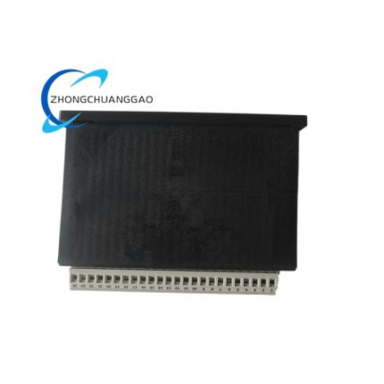
- Outer Module Shell: Cold-rolled steel sheet with anti-rust black electrostatic spraying treatment for cabinet rack fixed installation
- Rear Terminal Base: PA66 flame retardant plastic pedestal + nickel-plated oxygen-free copper anti-loose screw terminal posts for field wiring fixation
- Internal Fixed Fasteners: SUS304 stainless steel anti-corrosion screws and silicone shock-absorbing rubber pads for PCB internal fixed positioning
- Front Panel Adjustment Parts: metal shaft sealed precision wire-wound potentiometers with dustproof cap structure
- Surge Protection Components: ceramic gas discharge tube + TVS transient suppression diode set for PT input front-end overvoltage protection
7. Structural Features
- Split two-area internal layout inside metal casing: front parameter adjustment panel area, rear main PCB & terminal centralized wiring area.
- Six independent parameter trimming potentiometers sequentially arranged on upper front panel with engraved parameter name mark for on-site manual setting without equipment disassembly.
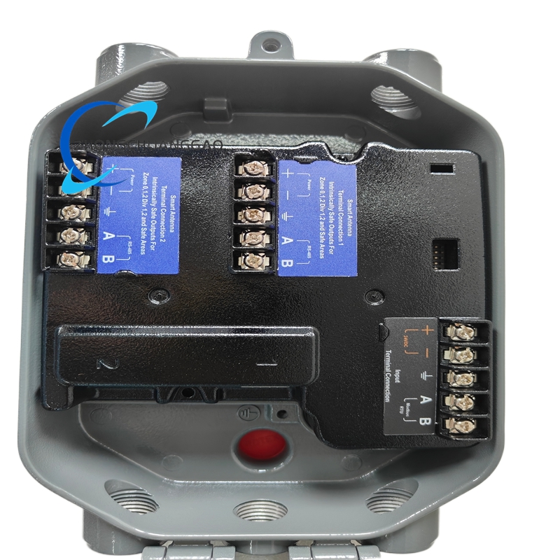
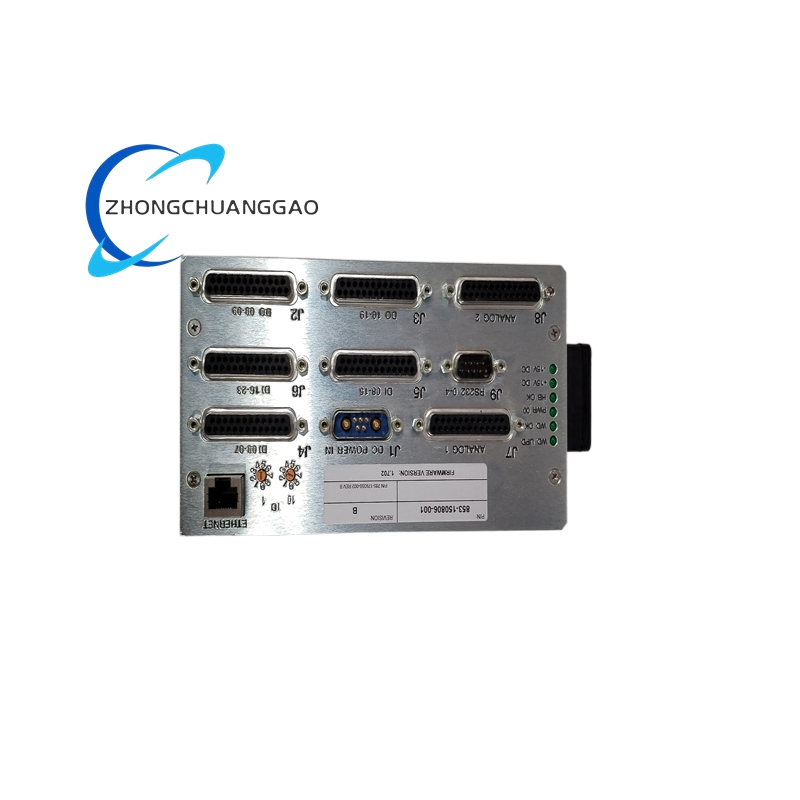
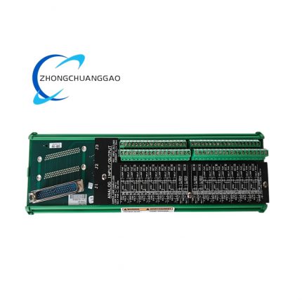
- All PT input, MPU speed input, governor bias output and breaker closing signal terminals uniformly arranged on rear panel with clear silk-screen signal definition marking for wiring identification.
- Four-corner pre-reserved fixed mounting holes around metal shell for standard cabinet panel embedded fixed installation.
- Multiple strip symmetrical heat dissipation slits distributed on left and right casing side walls to form natural air convection heat dissipation for internal heating electronic components.
- Independent isolation partition separates strong-current PT input circuit and weak-signal control circuit inside housing to reduce internal crosstalk interference.
8. Working Principle
Generator PT secondary voltage signal and busbar grid PT secondary voltage signal are introduced into corresponding module voltage input terminals; built-in front-end filter circuit eliminates wiring clutter and surge interference, then analog sampling circuit converts AC voltage signals into frequency, amplitude and phase corresponding DC deviation value. Internal multi-channel analog comparison circuit calculates real-time frequency difference, voltage difference and phase offset between two groups of input signals; according to preset threshold set via front potentiometers, control circuit outputs continuous adjustable analog bias signal to matching speed governor and AVR regulator. Speed bias signal changes engine fuel supply volume to adjust genset rotating speed and output frequency; voltage bias signal modifies AVR excitation output to adjust generator terminal voltage amplitude. When three items of frequency difference, voltage difference and phase angle all enter preset qualified window range, internal closing logic relay pulls in and outputs dry contact closing permission signal to generator inlet circuit breaker control loop to realize automatic synchronous closing. During whole running process, built-in damping circuit restrains overshoot adjustment caused by large engine inertia change, continuously real-time tracks parameter fluctuation of grid and generator for dynamic closed-loop correction.
9. Advantage Highlights
- Original factory pre-calibrated finished synchronizer with complete ex-factory test certificate, direct drop-in interchange replacement for same specification SPM-A series modules without secondary field calibration after installation.
- Dual-impedance output design covers full Woodward 2301/2301A/EPG mainstream governor models to reduce spare part inventory category of on-site maintenance warehouse.
- Full analog hardware control design free of program firmware avoids software crash failure risk under high electromagnetic interference industrial and marine harsh environment.
- Compact rack-mounted metal shell structure adapts standard industrial control cabinet layout to save cabinet internal installation space.
- Independent multi-point manual potentiometer adjustment mode allows on-site parameter quick modification adapting different diesel/gas/turbine engine dynamic characteristic without configuration software.
- Strict multi-condition closing interlock logic thoroughly eliminates out-of-step closing accident risk caused by single parameter abnormal fluctuation.
10. Applicable Industries
- Thermal Power Generation Industry: Coal/gas-fired distributed power plant standby generator automatic grid paralleling core control accessory
- Offshore Oil & Gas Industry: Offshore drilling platform fixed genset cabinet synchronization control unit for platform self-contained power grid
- Marine Shipbuilding Industry: Merchant vessel main/auxiliary diesel genset parallel power supply automatic synchronizing equipment
- Petrochemical Refining Industry: Refinery emergency black-start generator unit grid connection control component
- Mining Fixed Power Industry: Large underground mine emergency standby genset multi-unit busbar parallel synchronizer
- Island Microgrid Industry: Remote island independent microgrid distributed generator set automatic paralleling control equipment
11. Applicable Model Series
- Peer SPM-A Series Models: Woodward 9907-027,9907-030 different specification synchronization modules under SPM-A product line
- Matching Governor Products: Woodward 2301,2301A,723, EPG series electronic speed governors and corresponding electric fuel actuators
- Matching Auxiliary Accessories: Generator/grid PT potential transformer, MPU magnetic pickup speed sensor, shielded PT secondary signal cable, cabinet fixed mounting bracket
- Matching Supporting Parts: External closing intermediate relay, 115/230VAC cabinet auxiliary stabilized power supply
12. Installation Requirements
- Complete cabinet embedded fixed installation under full system power-off state, reserve minimum 30mm free ventilation gap above and below module shell for natural heat dissipation air circulation.
- Fasten four-corner fixing screws uniformly to avoid shell deformation caused by uneven fastening force during installation.
- Strictly follow rear terminal silk-screen definition for wiring: PT voltage signal cable adopts single-shielded twisted wire, separate weak-signal wiring and AC380V high-voltage power cable with minimum 15cm wiring spacing to avoid power frequency interference.
- Select 16AWG copper core wire for module AC power input wiring, connect module dedicated grounding terminal with independent single-point grounding wire to cabinet common earth busbar.
- Finish cabinet power supply switch-on and 25-minute preheating before formal commissioning, sequentially set frequency capture range, voltage matching margin, phase closing threshold via front panel potentiometers step by step according to genset rated parameter.
- Complete single unit no-load synchronization bench test before putting into field busbar parallel operation to verify closing action validity.
13. Usage Precautions
- Strictly prohibit powered state disassembly of metal outer shell and desoldering internal PCB components; arbitrary shell breaking invalidates original factory calibration parameter and voids product quality warranty.
- Prevent cabinet cooling water, engine lubricating oil and corrosive industrial gas splashing onto rear wiring terminal block; cut off module AC input power immediately once liquid contamination occurs and replace certified spare module directly.
- Forbid long-term overvoltage input exceeding 253VAC upper power limit; excess input voltage causes irreversible breakdown of internal power supply circuit semiconductor components.
- Execute quarterly fixed routine maintenance inspection: check terminal wiring fastening tightness, front potentiometer no loose slipping, synchronization closing action function and wiring insulation integrity, archive all inspection data into equipment maintenance ledger.
- Store unused spare module inside original factory anti-static sealed carton under 18℃~26℃ dry indoor warehouse environment, forbid long-term storage under direct sunlight, damp condensation or below -45℃ ultra-low temperature outdoor ambient.
- Avoid frequent short-interval repeated full power-on/power-off operation; every complete power-off standby interval exceeds 15 minutes to prevent cold-heat alternation fatigue leading to internal PCB solder joint open-circuit failure.


")
")


Reviews
There are no reviews yet.