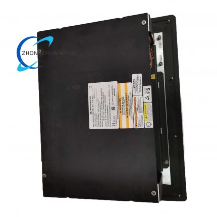
Product Brief Introduction
- Woodward 8440-2028 is factory pre-calibrated dedicated expansion module exclusively matched for Woodward easYgen-3100/3200XT genset main controllers, expanding original controller limited digital IO capacity to connect field auxiliary sensors, safety switches, alarm indicators and contact-type executive equipment.
- This module receives configuration instruction and real-time data via internal CAN bus communication from master easYgen controller, completing discrete signal collection of field digital input terminals and relay contact drive of digital output terminals independently.
- Every finished unit passes full-channel continuity test, relay on-off aging test, insulation withstand voltage inspection and CAN bus communication compatibility verification before factory shipment; all preset IO logic parameters are locked inside onboard nonvolatile memory chip after factory calibration.
- The product conforms to CE, UL and RoHS international industrial electrical certification standards, designed for indoor control cabinet DIN fixed installation inside genset automation control system.
3. Technical Specification
- Rated operating supply voltage: 24VDC, full allowable input voltage fluctuation range: 6VDC ~36VDC
- Nominal static working power consumption: 3.0W, maximum full-load total power consumption with all output relays closed: 4.7W
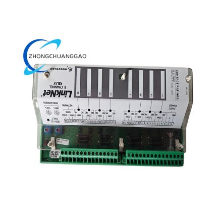
- Fixed channel configuration: 16-point galvanically isolated Digital Input (DI), 16-point potential-free relay Digital Output (DO)
- Digital input rated trigger voltage threshold: 12VDC~30VDC high-level effective; <5VDC low-level open circuit judgment
- Single-channel relay output rated contact specification: AC250V/5A, DC30V/5A resistive load fixed rating
- CAN bus communication standard: CAN 2.0B, fixed default baud rate: 250kbps, matching easYgen series master controller bus protocol
- Overall outer dimension: 168mm(L) × 50mm(W) × 130mm(H)
- Single bare module net weight: 0.46kg
- Cabinet installed protection grade: IP20 compliant with IEC60529 enclosure specification
- Continuous rated working ambient temperature range: -20℃ ~ +70℃; long-term storage extreme temperature range: -40℃ ~ +85℃
- Allowable working environment relative humidity: 5%RH~95%RH non-condensing, zero sulfur-containing corrosive gas and heavy dust accumulation condition
- Vibration resistance execution standard: IEC60068-2-6, continuously withstand 2.0g RMS vibration within 10Hz~500Hz frequency range under powered operation
- Compliance certification: UL508, CE-EMC, RoHS industrial electrical certification
4. Functional Features
- Sixteen fully independent galvanic-isolated digital input channels, each channel configures standalone optocoupler isolation circuit to eliminate field ground loop interference between different input signal loops.
- Sixteen groups of completely separated potential-free SPDT relay output terminals, every output channel corresponds to independent relay drive circuit without cross-channel load mutual influence.
- Dedicated CAN bus physical interface for data interaction with easYgen master controller; all channel definition, delay parameter and action logic are remotely configured via upper master controller without local hardware dial switch adjustment.
- Front panel equips 32 independent LED indicator lamps, 16 green DI status LEDs and 16 red DO action LEDs respectively; each LED corresponds to one fixed IO channel for real-time working status visualization display.
- Built-in full-channel fault self-diagnosis logic: automatically identify input overvoltage, output short-circuit and internal power abnormity; fault diagnostic codes upload to master controller via CAN bus synchronously once failure occurs.
- All input terminals integrate built-in TVS transient surge suppression components to absorb lightning impulse and power grid clutter transmitted via long-distance field wiring cable.
- Onboard non-volatile FLASH memory permanently stores user-configured channel logic parameters; stored data remains intact without external backup power supply after complete equipment power-off.
- Standard 35mm DIN rail fixed mechanical structure, supporting quick disassembly and replacement inside control cabinet without modifying peripheral wiring layout.
5. Performance Parameter
- Digital input signal sampling resolution under standard 25℃ environment: fixed 1ms single-channel sampling period
- Long-term continuous working input circuit zero drift: ≤0.03%FS per 24-hour uninterrupted full-load powered operation under constant ambient temperature
- Single-channel output relay mechanical service lifespan under rated resistive load: ≥1,200,000 standard switch action cycles
- Insulation resistance between internal power circuit and field IO terminal circuit: ≥1200MΩ measured by DC500V megohmmeter under normal temperature
- Dielectric withstand voltage between field wiring terminals and module metal fixed shell: AC1600V/1min without insulation breakdown and creepage discharge phenomenon
- Full signal response delay from field DI signal input to corresponding DO relay output action: ≤120ms fixed total processing cycle
- Anti-electromagnetic interference performance: maintain complete IO sampling accuracy under 10V/m RF field interference complying with IEC61000-6-2 standard
6. Material Composition
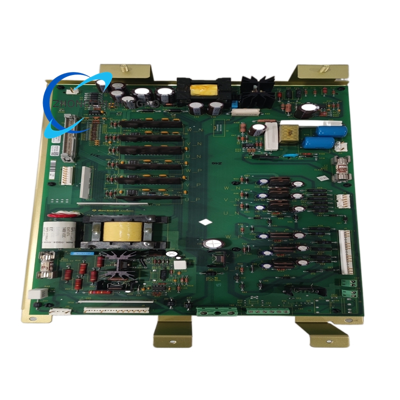
Main Core PCB Substrate
- PCB base raw material: FR-4 TG130 flame retardant epoxy glass fiber four-layer laminated board; power layer copper foil thickness 35μm, signal layer copper foil thickness 18μm, surface adopts lead-free HASL anti-oxidation coating treatment.
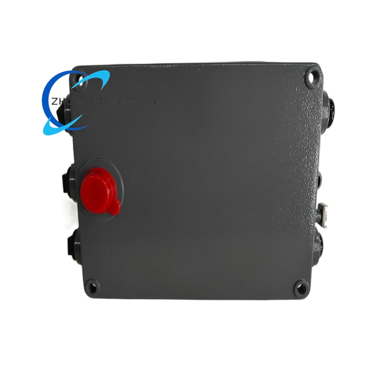
Outer Housing & Terminal Insulation Base
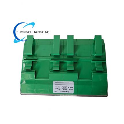
- Outer frame plastic housing: UL94-V0 flame retardant glass fiber reinforced PA66 nylon injection molding with anti-ultraviolet aging additive; wiring terminal plastic pedestal uses identical flame retardant insulating raw material.
Internal Core Electronic Components
- Input isolation device: high-speed wide-temperature industrial optocoupler chip; CAN communication master IC: automotive-grade CAN2.0B dedicated transceiver; relay drive unit: low saturation voltage SMD power triode.
- Output executive relay: sealed miniature SPDT electromagnetic relay with AgCdO silver alloy anti-arcing contact material for long service life; status indicator LED: epoxy sealed wide-temperature anti-vibration industrial LED component.
- Passive protection components: SMD TVS diode, high-temperature multilayer ceramic capacitor and polypropylene film fixed capacitor.
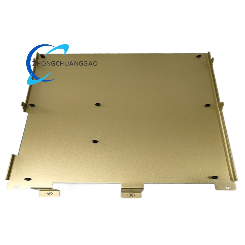
Fixed Fastening & Auxiliary Hardware
- All internal assembly locking screws: SUS304 stainless steel miniature anti-loose fasteners; DIN rail fixed clamping buckle: cold rolled SPCC steel plate with black matte electrophoretic anti-rust coating.
Optional Customized Variant Coating Material
- PCB three-proof protection coating: transparent acrylic anti-moisture anti-corrosion conformal paint for coastal high humidity and chemical corrosive site customized module versions.
7. Structural Characteristics
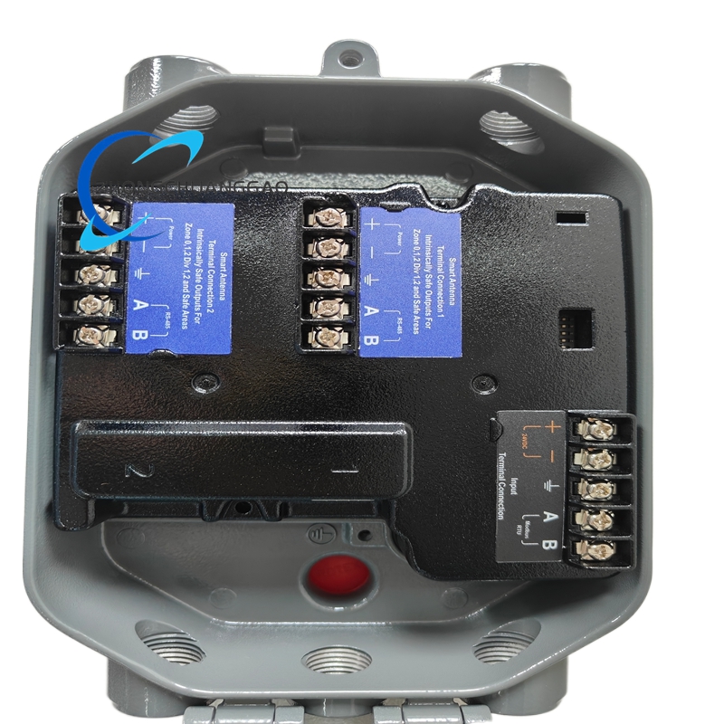
- Overall integrated rectangular DIN standard compact structure split into three fixed functional partitions: front panel indication area, middle core PCB circuit cabin, bottom side centralized wiring terminal region, fixed into complete unit via evenly distributed stainless steel anti-loose fasteners.
- Front panel fixed layout: green DI indicator bank and red DO indicator bank arranged in two equal-spacing horizontal rows, corresponding channel serial number silkscreen printed beside each indicator for rapid maintenance identification.
- Bottom side centralized terminal arrangement: all 32 IO wiring screw terminals partitioned by single-channel isolation spacing, functional definition including DI positive/negative and DO common/NO/NC marked directly on terminal pedestal.
- Left-side reserved CAN bus plug-in socket with physical anti-reverse insertion positioning notch to prevent reverse plug damage of communication wiring pin during field wiring construction.
- Upper shell surface reserved strip-shaped natural convection ventilation slots for internal relay heating component heat dissipation, avoiding over-temperature parameter drift of precision sampling circuit under long-term full-load continuous operation.
- Right-side blank marking area reserved on outer casing for manual labeling of cabinet number and corresponding genset equipment serial number for spare part inventory management work.
8. Working Principle
- External 24VDC rated working power accesses module internal isolated power conversion circuit, which outputs multiple groups of stable isolated DC working voltage for optocoupler input circuit, CAN communication circuit and relay drive circuit separately.
- Field digital switch signal inputs DI terminals, passes through optocoupler isolation and level conversion circuit to convert external discrete voltage signal into internal standard digital logic signal; onboard sampling circuit continuously collects real-time DI status data.
- Collected DI data packs into CAN bus data frame and transmits to matched easYgen master controller via internal CAN communication circuit; master controller executes preconfigured control logic algorithm based on uploaded input state.
- Master controller sends corresponding DO action instruction back to expansion module via CAN bus after logic operation; module internal drive circuit energizes designated output relay coil to complete contact pull-in or break action, driving external field alarm lamp, solenoid valve and auxiliary interlock equipment.
- Built-in terminal protection components absorb abnormal surge pulse voltage introduced by field long-distance cable lightning interference and power grid clutter to prevent false input triggering and relay misoperation.
- Internal fault detection circuit monitors power supply voltage, input overvoltage and output short-circuit state in real time; once abnormal condition is captured, fault flag uploads to master controller synchronously and corresponding channel indicator lamp changes fixed flashing state.
9. Advantage Highlights
- Exclusive original matching design for Woodward easYgen-3000 series genset controllers eliminates CAN bus communication mismatch risk caused by third-party non-original replacement expansion modules, guaranteeing complete channel parameter compatibility and factory calibrated precision.
- Full optocoupler isolation for all input channels cuts off ground loop interference between field multi-point different potential equipment, greatly lowering system false triggering rate under complex industrial site wiring environment.
- 16DI+16DO integrated high-density channel layout realizes centralized expansion of auxiliary control signals without installing multiple small-capacity auxiliary IO modules, simplifying internal cabinet wiring layout and reducing peripheral fault nodes.
- Remote parameter configuration via master controller cancels local hardware dial switch setting, realizing unified system logic modification in control room without on-site module disassembly operation.
- Wide-temperature industrial component selection enables stable continuous operation within -20℃~+70℃ without auxiliary cabinet forced cooling fan under conventional genset control cabinet environment.
- Standard DIN rail quick-install structure supports rapid disassembly replacement during equipment maintenance, cutting genset system downtime caused by faulty spare part overhaul.
- Potential-free relay output design matches all types of external AC/DC low-power executive equipment without additional intermediate relay conversion, improving field wiring construction efficiency.
10. Applicable Industries
- Diesel & Gas Generator Set Industry: Standby power genset, cogeneration unit auxiliary safety signal collection and interlock control cabinet IO expansion configuration, covering data center standby unit, hospital emergency power equipment.
- Petrochemical Industry: Refinery on-site backup gas genset, process pump auxiliary interlock signal expansion matching for combustible gas station power backup control system.
- Thermal Power Industry: Small-scale distributed biomass power station, waste incineration auxiliary genset safety protection signal collection deployment.
- Marine Power Industry: Vessel onboard emergency diesel genset control cabinet auxiliary switch and alarm equipment IO expansion installation.
- Mining Industry: Underground mine fixed standby power genset auxiliary monitoring and safety cut-off equipment signal expansion application.
- Construction Engineering Industry: Large commercial building centralized standby power station genset interlock control system peripheral signal expansion matching.
11. Model Series Classification
- Base standard model: 8440-2028 (Factory default bare module without matched wiring harness, standard indoor non-corrosive environment conventional version)
- Derivative variant 1: 8440-2028-CC (PCB full acrylic three-proof conformal coated customized model for coastal high-humidity and chemical corrosive gas working site)
- Derivative variant 2: 8440-2028-K (Complete accessory set model with factory pre-terminated 32-channel field shielded wiring cable and terminal plug accessories)
- Derivative variant 2: 8440-2028-LT (Low-temperature optimized component version for -40℃ minimum ambient temperature outdoor cabinet installation scenario)
12. Installation Requirements
- Cabinet pre-installation environment standard: Install inside IP42 and above closed standard metal control cabinet; keep module installation position over 80mm spacing away from cabinet internal AC contactor and high-power transformer strong magnetic field components.
- DIN rail installation specification: Snap module backside clamping buckle onto 35mm standard DIN rail horizontally, push down until buckle fully locks onto rail with fixed in-place feedback; forced prying of fixed buckle is strictly forbidden to avoid plastic housing damage.
- Field IO wiring construction rule: All field DI/DO signal wiring adopts single-core shielded cable; cable shielding layer single-end fixed grounding at cabinet PE protection ground bar, field equipment terminal shielding end suspended without grounding treatment.
- DC power wiring specification: Fetch 24VDC working power from cabinet isolated safety power supply; power ground wire connected to cabinet PE copper bus bar with conductor cross-section ≥0.75mm².
- Pre-power-on inspection requirement: After all field wiring connection finished, use multimeter to confirm no short-circuit between each terminal and module metal shell ground before switching on module total DC power supply.
- Post-installation preheating standard: Keep module continuous powered preheating for 20 minutes after DIN fixed installation before connecting CAN bus with master controller and downloading configuration parameters for formal system commissioning.
- Cabinet ventilation constraint: Keep rack surrounding ventilation space unobstructed without foreign object covering module upper heat dissipation ventilation slots to guarantee normal internal heat dissipation effect.
13. Usage Precautions
- Electrostatic protection regulation: Wear certified anti-static wristband reliably connected to cabinet PE ground bar when pulling out module or modifying CAN bus wiring; bare-hand direct contact with PCB circuit board and internal chip solder joint is strictly forbidden to avoid electrostatic breakdown of precision optocoupler and CAN communication components.
- Live operation restriction: Cut off module 24VDC total input power completely before any channel terminal wiring modification; live plugging/unplugging of field DI/DO signal cable during normal equipment running state is prohibited.
- Daily maintenance specification: Clean module outer surface accumulated floating dust every six months with dry compressed air at maximum 0.3MPa air pressure; avoid high-pressure air direct blowing to PCB welding spot and relay component area.
- Load constraint regulation: Strictly control single-channel external output load not exceeding rated 5A contact capacity; access of inductive load without freewheel diode parallel connection is forbidden to prevent relay contact ablation damage.
- Spare module storage standard: Store unused spare module inside original factory anti-static shielding carton under 15℃~25℃ dry constant-temperature warehouse environment, far away from corrosive chemical reagent and high dust concentration storage space.
- Fault disposal criterion: Cut off module total DC input power immediately once abnormal shell overheating, burnt component smell or continuous irregular indicator flicker occurs during operation; unauthorized disassembly of module outer shell and modification of internal original circuit layout are prohibited, contact Woodward official after-sales technical engineer for professional maintenance service.
- Long-term idle equipment management: If genset control cabinet stops continuous operation over 60 consecutive days, cut off module 24VDC input power; place desiccant bags inside closed cabinet to prevent internal PCB damp condensation corrosion and component aging failure.

")
")


-430x430.jpg)
-430x430.jpg)
-430x430.jpg)

Reviews
There are no reviews yet.