Product Brief Introduction
- This rotary actuator is core execution component of complete three-piece EPG governing system, which must match dedicated electronic speed controller and magnetic pickup sensor to constitute closed-loop engine speed regulation system.
- Rated for fixed 24VDC nominal working power supply, the component converts analog current command signal output from speed controller into mechanical rotary displacement to drive engine fuel rack, realizing continuous adjustment of fuel supply quantity for diesel, gasoline and gaseous fuel prime movers.
- Every finished unit completes full-stroke cycle aging test, torque calibration, low-high temperature cycling verification and full-function protection inspection before factory delivery, fully compliant with EU CE Directive and industrial UL safety certification standard.
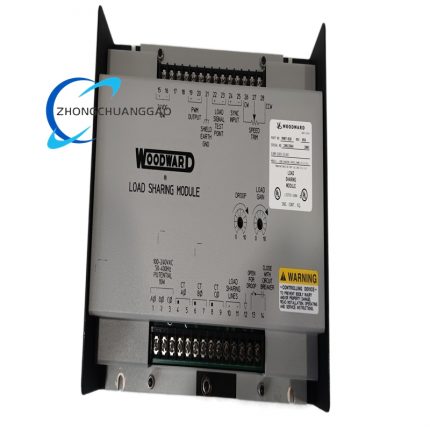
- The product supports single-unit independent governing or multi-unit load-sharing synchronous governing when paired with external parallel control accessory, applicable for single engine and genset paralleling power generation scenarios.
3. Technical Specifications (Core parameters marked in bold)
Electrical Specification
- Nominal Rated Operating Voltage: 24VDC, allowable continuous input fluctuation range: 20VDC~28VDC, transient instantaneous withstand voltage upper limit:32VDC within 100ms duration
- Maximum rated total power consumption: 60W, peak operating current under full-stroke output condition:3.6A RMS; static holding no-load current ≤0.8A at rated voltage
- Internal drive coil insulation grade: Class F, rated withstand coil voltage:120VAC 50Hz for 1 minute without breakdown
- Control signal receiving standard: DC variable current analog signal matching Woodward EPG controller, command signal range:4mA~20mA full span corresponding to full mechanical travel stroke
- Permitted maximum wiring length: 11m for 14AWG control cable, 23m for 12AWG thickened copper wiring under standard 24VDC power supply layout
- Ambient working temperature range: -40℃~+93℃ (-40℉~+200℉) continuous rated operation, certified long-term storage temperature range:-45℃~+100℃
- Environmental humidity standard: 5%~95% non-condensing relative humidity; internal component contact with condensed liquid is permanently forbidden
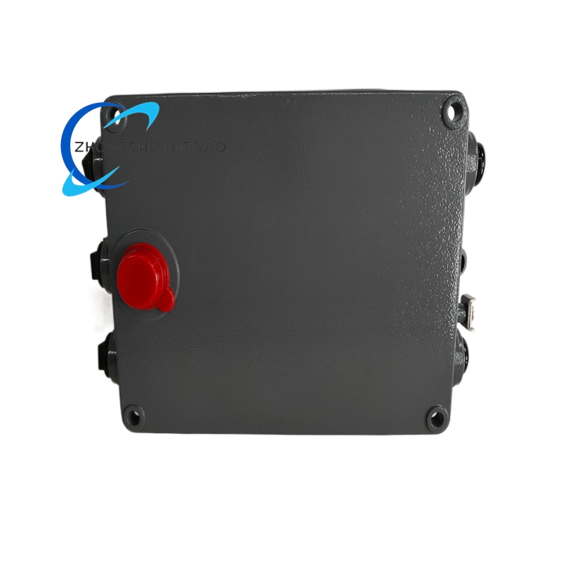
- Enclosure protection grade: IP65 fully sealed housing structure, effective dustproof and splash-proof protection for on-engine harsh installation environment
Mechanical & Output Specification
- Total effective mechanical rotary travel angle: 35° full stroke, bidirectional clockwise and counterclockwise equal rotation travel range with built-in mechanical overtravel limiting stop structure
- Rated full-stroke output torque:3.4N·m (30in-lb), minimum startup driving torque ≤0.32N·m at 22VDC lower limit working voltage
- Output shaft specification: 0.375inch-36 standard SAE serrated double-end spline shaft, both shaft ends adopt unified spline dimensional specification for interchangeable linkage assembly
- Full-stroke mechanical response time: ≤30ms from minimum to maximum rated output displacement under standard rated power input condition
- Single unit net weight: 454g (1.0lb), original factory sealed packing gross weight:620g including installation gasket and specification document
Matching System Specification
- Compatible magnetic pickup frequency matching: 3000Hz~6000Hz for diesel engine and gas engine equipped with startup fuel limiting structure;6000Hz~12000Hz for conventional gasoline/gaseous fuel engine without fuel limit setting
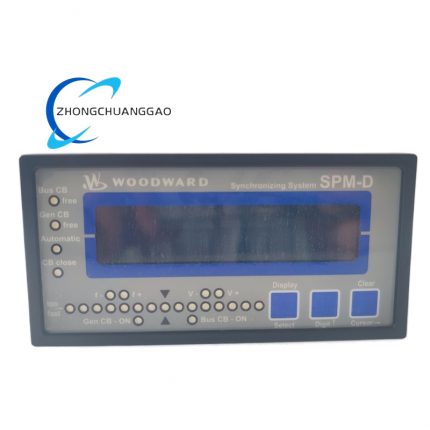
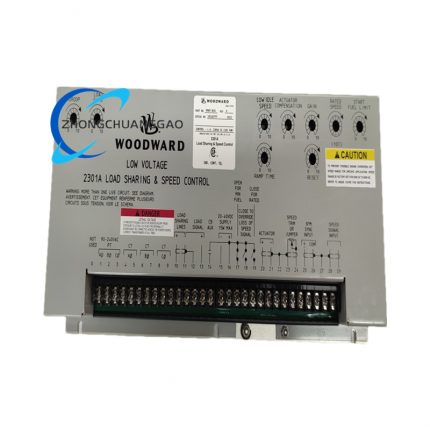
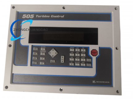
- Matching controller series: Woodward 1724 EPG speed control unit, 2301A, 2301D, 5300 series digital engine governors
- Auxiliary switch rated parameter: Built-in idle/rated auxiliary contact switch, fixed contact rated capacity: 10A/250VAC single-pole single-throw switching specification
4. Functional Features
- Closed-loop fuel adjustment execution function: Convert variable current control signal from external speed controller into proportional rotary displacement to pull engine fuel control rack, linearly change fuel injection quantity according to speed deviation command.
- Dual-mode governing logic matching function: Support field switch configuration for isochronous constant-speed control and droop proportional speed regulation two core governing modes to satisfy standalone genset and grid-parallel genset different operating requirements.
- Built-in mechanical overtravel protection function: Fixed mechanical limit stoppers at two ends of full rotation stroke prevent output shaft overtravel damage caused by abnormal over-range control signal input.
- Integrated idle speed lock auxiliary switching function: Terminal 5 external DC control voltage (10~40VDC) input controls auxiliary contact status; contact open locks engine idle speed, contact closed releases rated speed acceleration operation.
- Internal reset spring automatic homing function: Built-in high-strength return spring pulls output shaft back to minimum fuel idle position immediately after cutting off actuator working power supply.
- Selectable acceleration ramp adjustment function: Matching external potentiometer adjusts idle-to-rated speed acceleration time from ≤1s to 22s fixed adjustable range via peripheral controller parameter setting.
- Full internal short-circuit & overcurrent hardware protection function: Embedded power drive circuit protection cuts coil drive output instantly once internal winding short-circuit occurs to avoid permanent coil burnout.
5. Performance Parameters
Motion Control Precision Index
- Full stroke linearity error between input control current and mechanical output travel: ≤±2.1%FS under 25℃ rated ambient environment
- Output shaft positioning repeat accuracy: ≤±0.3° mechanical angle after repeated full-stroke reciprocating movement
- Zero-point idle position drift: ≤±0.4° mechanical travel within continuous 24h no-load stable energized working condition
Reliability Lifespan Index
- Rated continuous service life: Minimum 45000 hours stable continuous operation under non-corrosive standard engine mounting environment per factory specification
- Vibration durability compliance: Pass IEC60068-2-6 standard 10Hz~200Hz full frequency sweep vibration test conforming to on-engine mechanical vibration working condition
- Temperature cycling reliability: No performance parameter deviation after 1000 cycles of -40℃ ↔ +93℃ alternate temperature cyclic test
Anti-interference Performance Index
- Power supply ripple resistance: Allow input DC supply peak-to-peak ripple ≤15% rated 24VDC without abnormal jitter of output shaft travel
- On-engine electromagnetic interference tolerance: Conform to IEC61000-6-2 industrial EMC standard, maintain stable output under ignition coil and starter electromagnetic interference environment
6. Material Composition
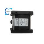
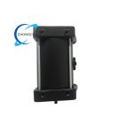
- Outer Main Housing: Die-cast ADC12 aluminum alloy shell with anti-corrosion epoxy paint surface coating, integral sealing groove for IP65 rubber sealing ring installation.
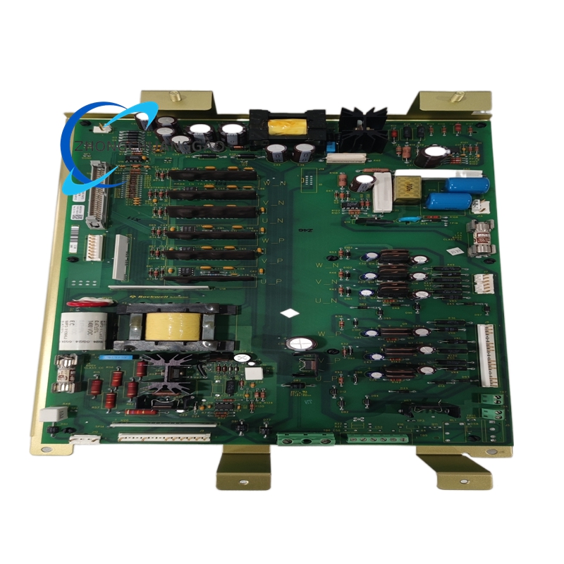
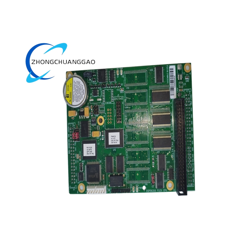
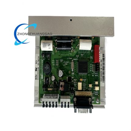
- Internal Drive Core Components: High-purity copper enameled wire wound electromagnetic drive coil with Class F high-temperature insulation paint; silicon steel laminated stator iron core and permanent magnet rotor assembly for electromagnetic driving.
- Output Transmission Mechanism: 40Cr quenched alloy steel gear set and spline output shaft with anti-rust zinc plating surface treatment; high-temperature lithium grease pre-filled sealed rolling bearings for rotary support.
- Built-in Reset Component: High-carbon spring steel formed return torsion spring with passivation anti-corrosion surface processing.
- Terminal & Sealing Parts: Glass-filled PA66 flame retardant plastic terminal base; EPDM high-temperature resistant rubber integrated sealing ring for shell split surface waterproof and dustproof isolation.
- Internal auxiliary switching component: Silver alloy contact mechanical microswitch installed inside housing for idle-rated status signal conversion.
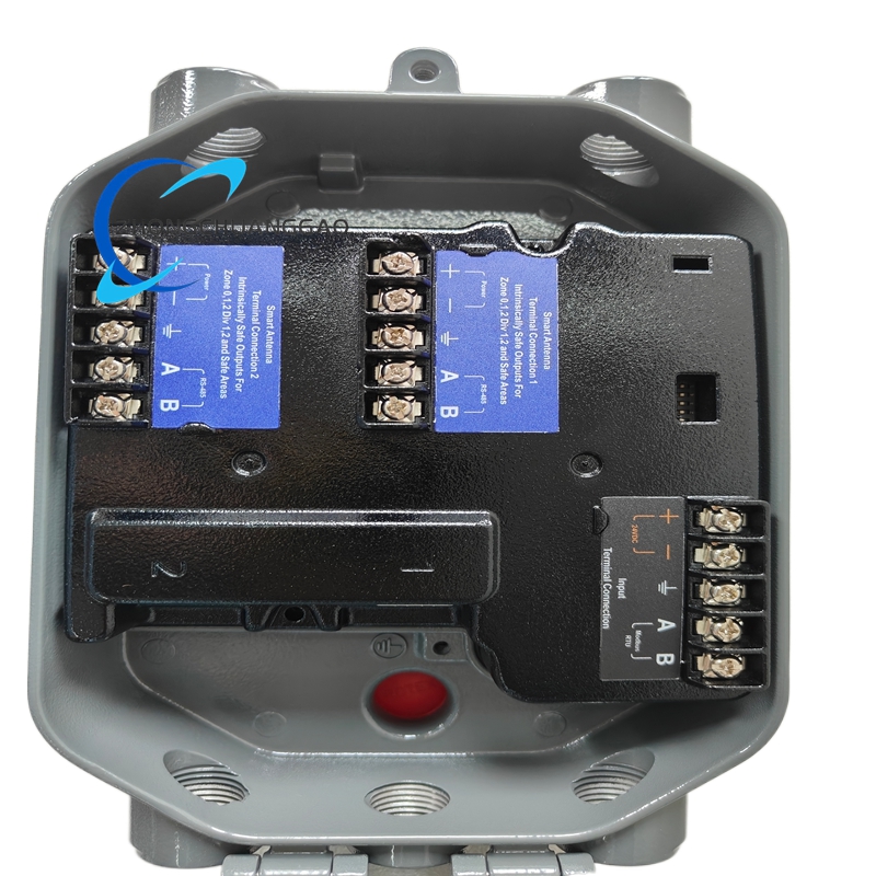
7. Structural Characteristics
- Split two-stage sealed housing layout: Upper terminal wiring cavity and lower mechanical transmission drive cavity separated by intermediate aluminum isolation partition plate, independent sealed space for circuit and mechanical parts respectively.
- Double-end uniform spline output shaft structure: Consistent 0.375inch-36 SAE serrated spline design at both shaft terminals to realize bidirectional linkage mounting interchangeability without accessory replacement.
- Foot-flange dual-purpose fixed mounting base: Four symmetrical mounting threaded holes distributed on base flange for flat foot mounting and engine flange direct installation two fixed modes.
- External adjustable stroke limit structure: Two external set screws on shell sidewall adjust two-end maximum mechanical travel position without disassembling sealed housing.
- Internal pre-grease enclosed transmission structure: Gear and bearing components fully enclosed inside oil storage cavity with factory pre-filled high-temperature lubricating grease, no periodic on-site refuel maintenance required.
8. Working Principle
- DC Power Input Stage: External 24VDC rated working power enters internal power conditioning circuit after passing external fuse and control wiring, converted into stable low-voltage auxiliary power for internal auxiliary switch and drive pre-circuit.
- Command Signal Receiving Stage: 4~20mA analog current signal from matched Woodward speed controller is input to internal electromagnetic drive coil; coil generates variable magnetic field intensity proportional to received current value.
- Electromagnetic Conversion & Mechanical Drive Stage: Variable magnetic field drives permanent magnet rotor and gear transmission mechanism to produce corresponding rotary displacement; input current increase drives output shaft toward maximum fuel position, current decrease drives shaft toward minimum idle fuel position.
- Return Spring Counterbalance Stage: Built-in torsion spring applies opposite reset torque against electromagnetic driving torque, forming torque balance relation between spring force and electromagnetic force to fix output shaft at corresponding fuel opening position matching input signal.
- Auxiliary Switch Status Conversion Stage: When external 10~40VDC control voltage accesses terminal 5, internal auxiliary switch flips status to lock minimum fuel idle position; voltage removal releases idle lock to allow acceleration stroke movement.
- Power-off Reset Stage: After cutting off main 24VDC working power supply, reset spring overcomes residual magnetism torque and pulls output shaft back to factory default idle zero-fuel position automatically.
9. Advantage Highlights
- Wide ambient temperature adaptability covering -40℃~+93℃ working range, stable performance for high-temperature engine exhaust peripheral and low-temperature outdoor genset harsh installation environment.
- IP65 fully sealed aluminum alloy anti-corrosion housing adapts to engine oil mist, splash water and dusty on-engine installation condition to reduce early internal component failure probability.
- Unified double-end SAE spline output shaft realizes universal matching with mainstream engine fuel rack linkage accessories without customized mechanical modification.
- Dual isochronous/droop built-in governing mode switches flexibly switch between standalone unit and grid-parallel genset application scenes without additional external control module purchase.
- Built-in mechanical overtravel stop and multi-level internal circuit protection avoid damage caused by wiring error, abnormal over-range control signal and power supply fluctuation.
- Pre-filled lifelong high-temperature bearing grease design eliminates regular field disassembly lubrication maintenance, cuts post-installation maintenance cost and workload.
- Complete matching compatibility with full Woodward EPG controller series and mainstream domestic and foreign diesel/gas engine fuel control linkage structure.
10. Applicable Industries
- Power Generation Industry: Fixed diesel/gas genset standalone speed control, multi-unit synchronous parallel grid-connected power station fuel regulation, emergency standby generator set governing configuration.
- Petroleum & Gas Industry: Oilfield site portable gas-drive prime mover speed control, natural gas compressor prime mover fuel adjustment, offshore platform backup diesel engine governing.
- Marine Equipment Industry: Small inland watercraft auxiliary diesel engine fuel control, ship emergency backup genset speed regulation system matching.
- Construction Machinery Industry: Large engineering machinery stationary auxiliary diesel power unit fuel rack driving, mine fixed standby diesel engine governing assembly.
- Petrochemical Processing Industry: Factory on-site waste gas combustion gas engine speed control, chemical plant emergency backup generator fuel adjustment system.
11. Model Series Classification
- Parent Product Line: Woodward EPG Full Series Electric Rotary Governor Actuator Family
- Same-series core derivative model classification:
- 8256-012: 12VDC low-voltage variant with identical mechanical stroke and torque specification for 12V battery-powered small genset
- 8256-016: Standard 24VDC mainstream industrial model (archived target product) with full IP65 sealing and dual governing mode configuration
- 8256-022: High-torque enhanced variant with 5.2N·m output torque for large-bore heavy-duty diesel engine matching
- Compatible matching controller product series: Woodward 1724, 2301A, 2301D, 5300 digital EPG speed control modules
12. Installation Requirements
- Flange Mounting Specification: Use M6 high-strength anti-loose bolts to fasten actuator base flange onto engine fixed mounting pad; single bolt fastening torque controlled at 2.2~2.6N·m, install anti-slip sealing gasket between base and mounting surface, avoid gasket blocking base drain holes.
- Linkage Assembly Specification: Connect output spline shaft with engine fuel rack linkage via standard SAE spline sleeve, ensure linkage free movement without clamping stagnation and excessive assembly clearance; adjust linkage stroke to match actuator full 35° mechanical travel range.
- Wiring Specification: Power main circuit adopts ≥1.0mm² stranded copper cable; control signal wire uses shielded twisted copper wire, shield layer single-end grounded only at controller side without connecting actuator housing; separate power wiring and signal wiring with ≥25mm spacing to prevent electromagnetic crosstalk.
- Ambient Installation Restriction: Install actuator away from engine exhaust direct radiant heat source and continuous liquid splash area, reserve ≥40mm free ventilation space around shell periphery for natural heat dissipation.
- Pre-commissioning Inspection Rule: Complete full wiring continuity and short-circuit inspection before first power-on energization; manually toggle output shaft full stroke twice to confirm no mechanical clamping stagnation before connecting rated 24VDC working power.
13. Usage Precautions
- Power-on Preheating Regulation: After connecting rated 24VDC power supply, keep actuator idle energized for minimum 8 minutes preheating before formal speed regulation debugging to stabilize internal coil working temperature and output torque consistency.
- Parameter Adjustment Regulation: External acceleration ramp potentiometer adjustment must be executed under power-off state; excessive clockwise/counterclockwise potentiometer rotation damages internal precision resistance component permanently.
- Disassembly Forbidden Regulation: Non-Woodward certified maintenance personnel are prohibited from disassembling sealed aluminum housing; split shell destroys internal IP65 sealing structure and invalidates original factory product warranty.
- Long-term Idle Storage Specification: Remove all external wiring after dismounting actuator for idle storage over 30 days, coat output spline shaft with anti-rust grease, place inside original sealed moisture-proof carton under 10℃~35℃ dry indoor environment away from corrosive volatile gas.
- Anti-contamination Control Regulation: Prevent engine fuel oil, hydraulic oil and corrosive chemical liquid from splashing onto shell sealing gap; long-term liquid infiltration causes internal bearing rust and drive coil insulation aging failure.
- Periodic Maintenance Regulation: Complete annual routine inspection under power-off state including fastening mounting bolts, checking linkage wear condition and wiping shell surface dust with dry compressed air; replace damaged spare parts exclusively with Woodward original certified accessories.

")
")


-430x430.jpg)
-430x430.jpg)

Reviews
There are no reviews yet.