Product Brief Introduction
- This unit is factory standardized compact microstepping drive developed for two-phase hybrid stepper motors, which converts external TTL step/direction control pulse signals into adjustable PWM winding driving current to realize precise position and speed control of matched two-phase stepper equipment.
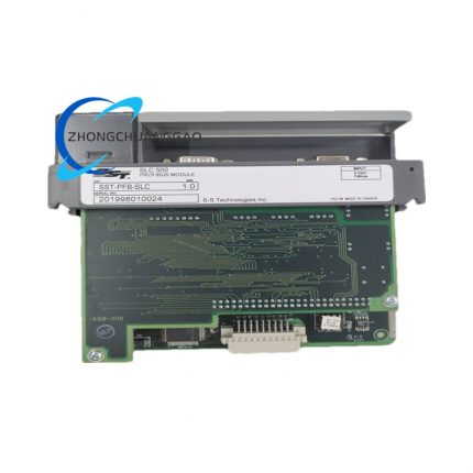
- The model 6410-024-N-N-N is configured with factory default 5A RMS rated output specification, no factory pre-installed outer casing, independent heat sink and matching terminal connector accessory, all structural spare parts are optional aftermarket purchase items.
- Every finished drive undergoes full-load continuous aging test, parameter calibration and multi-item protection function verification under 24VDC and 75VDC extreme input voltage before factory delivery, conforming to UL508C and IEC61131-2 international industrial safety certification standards.
- It supports flexible parameter configuration via onboard DIP switches and jumper terminals to adjust output current, microstep subdivision ratio, idle current reduction and signal filter mode for diversified on-site motor matching demands.
3. Technical Specifications (Core parameters marked in bold)
Electrical Specification
- Rated DC Power Input Range: 24VDC~75VDC single-ended non-isolated power supply, maximum instantaneous peak input current:8.2A, normal average input current ≤5.1A under full-load rated working state
- Output Current Parameter: 0.625A~5.0A RMS per phase adjustable in 0.625A incremental step; peak output current reaches 7.1A under microstepping working mode, 5A RMS is factory fixed default setting for 6410-024-N-N-N
- Internal PWM Chopping Frequency: Fixed 20kHz constant high-frequency chopping frequency for bipolar winding current regulation
- Control Signal Interface Standard: Optocoupler isolated TTL level step/direction input, isolated input driving current range:5.5mA~10mA DC
- Pulse Timing Index: Minimum valid input pulse width:250ns without signal filter; filtered mode minimum pulse width expands to 1μs; maximum response input frequency:2MHz (filter bypass), 500kHz (filter enabled)
- Ambient Temperature Standard: Continuous rated operating temperature: 0℃~+50℃, certified long-term component storage temperature:-20℃~+70℃
- Environmental Humidity Rating: 5%~90% non-condensing relative humidity for continuous running; condensed moisture accumulation inside casing is permanently prohibited
- Ingress Protection Grade: Standard IP20 protection rating for exposed circuit mainboard structure
Microstep & Control Specification
- Available Microstep Subdivision Range: Full step~1/256 microstep adjustable via DIP switch and decimal/binary selection jumper, compatible with standard 1.8° step angle two-phase stepper motor (200 full steps per mechanical rotation)
- Idle Current Reduction Timing: Configurable idle delay via onboard jumper:0.05s / 0.1s / 1.0s three fixed delay options, drive automatically reduces winding holding current after preset idle period to cut power loss
- Electronic Damping Function: Hardware switch selectable enable/disable mode to eliminate mid-speed mechanical resonance of matched stepper motor
Physical Dimension Specification
- Overall Outer Dimension: 127mm (Height) ×38.1mm (Width) ×109.2mm (Depth), corresponding imperial size:5.05in ×1.5in ×4.3in
- Net Single Unit Weight: 320g, original factory export packing gross weight:445g without optional casing and heat sink accessory
- Mounting Hole Standard: Four fixed circular mounting holes with 4.2mm inner diameter distributed at four corners of base plate, fixed hole center spacing:115mm×26mm for DIN rail or flat panel locking installation
4. Functional Features
- Bipolar PWM Chopping Drive Function: Adopts full-bridge bipolar chopping topology to output constant-amplitude adjustable current for two-phase stepper motor winding, realizes stable torque output under variable working speed.
- Optocoupler Isolated Signal Receiving Function: All external step/direction control signals pass high-speed optocoupler isolation circuit to block industrial site power grid electromagnetic interference from control loop.
- Multi-Grade Output Current Configuration Function: Three-bit onboard DIP switch realizes eight-level fixed RMS current selection from 0.625A to 5A to match different specification two-phase stepper motors ranging from small torque to large torque type.
- Full-Range Microstep Adjustment Function: Dual control of DIP switch and setting jumper switches decimal/binary subdivision arithmetic to realize continuous subdivision from full step down to 1/256 microstep for high-precision low-vibration operation.
- Automatic Idle Current Drop Function: After preset motor static idle time expires, drive actively lower winding holding current to reduce coil heating and no-load power consumption of whole system.
- Full-Range Hardware Protection Function: Integrated overvoltage, undervoltage, output short-circuit, overcurrent and internal overheating five-level hardware protection circuit; drive cuts output power automatically and locks fault state once abnormal working condition triggers protection threshold.
- Fault Auto-Reset Function: After external abnormal fault is eliminated and input power recovers to rated range, drive completes automatic fault reset and resumes normal driving output without manual hardware operation.
5. Performance Parameters
Motion Control Precision Index
- Full-step positioning repeat accuracy: ≤±0.03 mechanical step under standard 25℃ rated ambient environment
- Microstep positioning error: ≤±2.5%FS of single subdivided step within full 1/2~1/256 subdivision working range
- Low-speed operation vibration suppression rate: ≥92% vibration reduction effect after enabling built-in digital electronic damping function at 10~300RPM motor rotating speed section
Electrical Reliability Index
- Continuous full-load working lifespan: Minimum 50000 hours stable running under rated input voltage and standard non-corrosive industrial environment per factory specification
- Surge voltage resistance capacity: Can withstand instantaneous ±20% rated input voltage surge impact within 100ms duration without internal component damage
- Protection action response speed: ≤8μs response time for output short-circuit protection trigger; ≤150ms response time for over-temperature protection trigger
Anti-interference Performance Index
- Power supply ripple interference tolerance: Allows input DC power supply ripple peak-to-peak value ≤12% of rated input voltage without output current distortion
- External electromagnetic interference resistance: Conforms to IEC61000-6-2 industrial anti-EMC standard, keeps normal control output under common on-site frequency converter and relay switching interference environment
6. Material Composition
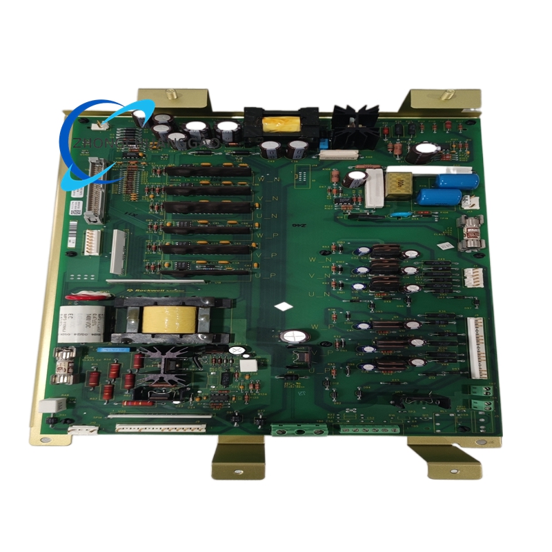
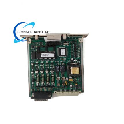
- Main Control Circuit Baseboard: FR-4 grade fire-retardant epoxy resin printed circuit board with UL94-V0 flame resistance certification, copper foil thickness 35μm for internal circuit wiring.
- Power Switching Core Components: Imported N-channel power MOSFET with TO-252 encapsulation, silicon-based high-speed switching transistor as PWM chopping power core.
- Onboard Adjustment Components: Carbon film fixed DIP switches, phosphor bronze alloy jumper terminals, metal oxide film fixed resistors and polyester non-polar capacitors for parameter setting circuit.
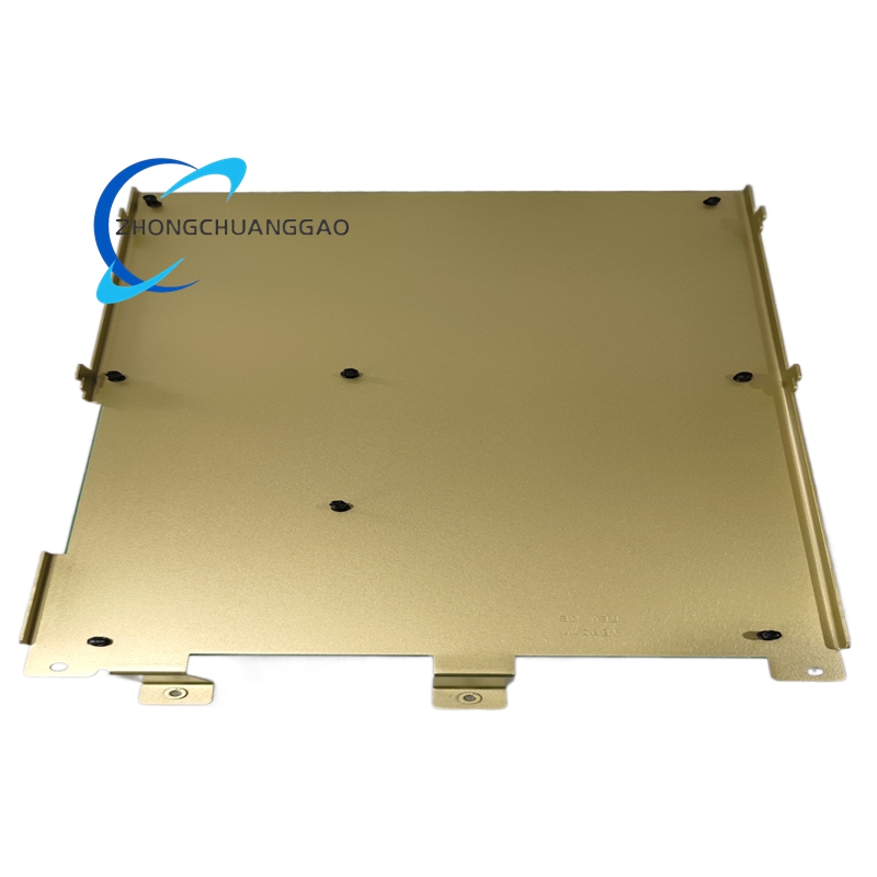
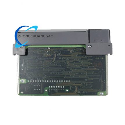
- Bottom Mounting Base Plate: Cold-rolled SPCC steel plate with black anti-rust electrophoretic coating for overall mechanical fixation of circuit board.
- Isolation Components: GaAs-based high-speed linear optocoupler chip for control signal isolation between external PLC and internal drive circuit.
7. Structural Characteristics
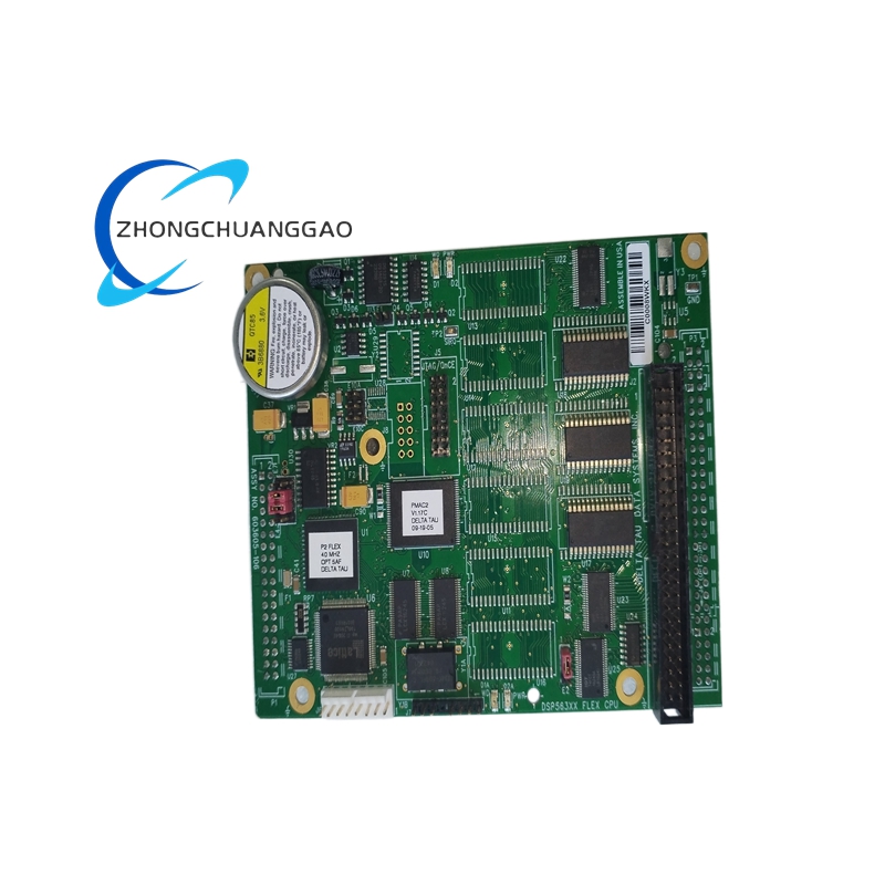
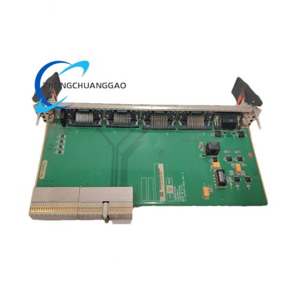
- Integrated single-layer flat mainboard layout structure: All power circuit, control circuit and parameter configuration terminals are concentrated on one unified PCB board without split modular separation design.
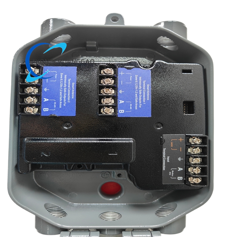
- Partitioned terminal layout: Left side centralized power input terminal group, middle onboard DIP switch and parameter jumper area, right side motor winding output terminal and control signal input terminal group for wiring zoning management.
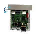
- No pre-installed outer housing structure: Factory delivery state is bare circuit board matching base steel plate without upper protective plastic shell; outer cover belongs to optional aftermarket accessory item for 6410-024-N-N-N model.
- Passive heat dissipation structural design: No factory pre-equipped aluminum alloy heat sink; heat dissipation depends on base steel plate contact with external cooling flat plate via surface conduction mode.
- Four-corner fixed installation structure: Four symmetric positioning mounting holes at base steel plate four corners, compatible with DIN35 standard guide rail clamping and flat screw locking two installation modes.
8. Working Principle
- DC Power Supply Conversion Stage: External 24~75VDC industrial DC power inputs to drive internal power management circuit, which converts raw input voltage into multi-channel stable low-voltage DC to supply MCU control core, optocoupler isolation circuit and auxiliary parameter setting circuit respectively.
- Control Signal Isolation Receiving Stage: External PLC or motion controller outputs TTL step pulse and direction level signal, which passes optocoupler isolation to eliminate ground loop interference and transmits isolated digital signal to internal main control microprocessor unit.
- Parameter Loading Calculation Stage: Onboard DIP switch and jumper preset parameters (output current, subdivision ratio, idle delay, damping status) are read by MCU after power-on initialization; MCU calculates corresponding PWM modulation waveform according to received step pulse frequency and preset subdivision data.
- PWM Chopping Current Output Stage: MCU outputs adjustable duty-cycle PWM signal to drive power MOSFET full-bridge circuit; bipolar full-bridge converts fixed DC input into constant average adjustable AC winding current to drive two-phase stepper motor coils and realize electromagnetic stepping rotation.
- Idle Current Regulation Stage: When no new step pulse is received after preset idle delay time, MCU automatically reduces output average current to lower motor holding power loss; new incoming step signal triggers instantaneous recovery of rated output driving current.
- Hardware Protection Execution Stage: When overvoltage, short-circuit or overheating abnormal condition occurs, dedicated hardware protection comparator sends locking signal to MCU, drive immediately cuts all MOSFET output and enters fault locked state until external fault is cleared and power restarts.
9. Advantage Highlights
- Compact ultra-small volume design occupies only 48.4cm² installation space, saves cabinet internal layout space compared with traditional split large-size stepper drive products.
- Wide single-power input voltage range of 24~75VDC realizes direct matching with most standard industrial DC switching power supply without extra step-down transformer configuration.
- Full step to 1/256 ultra-high microstep subdivision capability drastically suppresses low-speed cogging vibration and operating noise of matched two-phase stepper motor.
- Patented digital electronic damping hardware design effectively eliminates inherent mid-speed resonance defect of hybrid stepper motor to expand stable available rotating speed range of whole motion system.
- Independent idle current reduction function lowers long-term no-load power consumption and coil heat accumulation to extend overall service life of matched stepper motor.
- Full five-level hardware protection system avoids irreversible damage caused by wiring error, power surge and abnormal load short-circuit to drive and matched stepper motor.
- Standard TTL optocoupler isolated interface realizes seamless compatibility with mainstream PLC, motion controller and CNC system brands worldwide without extra signal conversion module.
10. Applicable Industries
- Precision Automation Equipment Industry: SMT chip mounting equipment feeding axis control, PCB automatic routing machine positioning drive, small automatic dispensing machine linear motion control.
- Packaging Machinery Industry: Vertical bag making machine feeding roller drive, carton automatic sealing equipment positioning axis, label sticking machine stepping positioning control.
- Medical Equipment Industry: Medical laboratory automatic sampling instrument motion drive, CT auxiliary bed small displacement positioning mechanism, pharmaceutical pill sorting equipment stepping control.
- Textile Machinery Industry: Small jacquard loom needle selection stepping drive, automatic yarn winding machine feeding axis motion control.
- Semiconductor Auxiliary Equipment Industry: Wafer small displacement clamping positioning mechanism, chip testing equipment precision stepping conveying control.
- Printing Equipment Industry: Small digital printer paper feeding stepping drive, flexo printing machine color register fine adjustment control axis.
11. Model Series Classification
- Parent Product Line: Pacific Scientific 6000 Series Microstepping Stepper Drive Family (6410 Core Sub-series)
- Same-series core derivative model classification:
- 6410-001-N-N-N: Default 3A RMS medium current standard version with optional factory pre-installed casing and heat sink
- 6410-009-N-N-N: High anti-interference customized variant for severe electromagnetic interference industrial cabinet environment
- 6410-024-N-N-N: 5A RMS full-power bare-board standard model (target archived unit, no factory casing/heat sink/connector)
- Compatible matching stepper motor series: Pacific Scientific POWERPAC two-phase hybrid stepper motor full specification range, third-party NEMA17/NEMA23/NEMA34 standard two-phase stepper motors
12. Installation Requirements
- Flat Plate Mounting Specification: Fix base steel plate onto metal cooling flat plate with M3 standard machine screws, keep full contact between base plate and cooling surface to realize passive heat conduction dissipation; mounting flat plate minimum thickness ≥3mm cold-rolled steel plate.
- DIN Rail Mounting Specification: Match standard DIN35 top-hat guide rail via optional aftermarket DIN clamping accessory, clamping torque controlled at 0.8~1.2N·m to avoid base plate deformation.
- Wiring Specification: Power input cable adopts 1.0mm² and above stranded copper wire; motor winding output wire uses 0.75mm² and above shielded twisted cable; control signal wire selects 0.5mm² shielded wire, separate power wiring and signal wiring with spacing ≥20mm to avoid cross electromagnetic interference.
- Cabinet Environmental Installation Restriction: Install inside closed control cabinet with effective cabinet ventilation; ambient air flow around drive surface shall not be blocked by other adjacent electrical components, reserved ≥30mm free clearance space around four sides of drive.
- Pre-power-on Inspection Rule: Complete all wiring continuity and short-circuit inspection before first power input; confirm DIP switch and jumper parameter setting match actual matched motor specification before energization.
13. Usage Precautions
- Power-on Preheating Regulation: After rated DC power input, keep drive idle energized for minimum 5 minutes preheating before formal stepping operation to stabilize internal component working temperature and parameter consistency.
- Parameter Modification Regulation: All DIP switch and jumper parameter adjustments must be operated after complete input power cut-off; parameter modification under live power status will trigger instantaneous output current mutation and motor abnormal shock damage.
- Heat Dissipation Management Regulation: For continuous full-load long-time operation above 8 hours daily, purchase matching aftermarket aluminum heat sink accessory and install on drive power MOSFET area to strengthen heat dissipation effect.
- Storage Specification: When drive is uninstalled and idle over 30 days, place inside sealed moisture-proof antistatic plastic bag and store under 10℃~35℃ dry indoor environment, avoid high humidity and corrosive gas ambient storage.
- Wiring Forbidden Regulation: Never perform live plugging/unplugging of motor winding terminal and power input terminal; live plug operation causes instantaneous short-circuit and permanent internal power component burnout.
- Periodic Maintenance Regulation: Every 12 months complete terminal screw fastening inspection and dust cleaning of PCB surface with dry compressed air under power-off state; replace aged wiring and damaged terminal accessories exclusively with Pacific Scientific original certified spare parts.

")
")


Reviews
There are no reviews yet.