Technical Specifications
- Module Form Factor: Single-wide CTI 2500 series rack module
- Physical Dimensions (W × H × D): 100 mm × 85 mm × 70 mm
- Net Module Weight: 0.68 kg (1.5 lbs)
- Backplane Maximum Power Draw: 3 W DC 24 V
- Total Analog Input Channels: 8 isolated channels
- Total Analog Output Channels: 4 isolated channels
- Analog Input Signal Ranges (Per Channel Selectable): 0–5 V DC, 0–10 V DC, 0–20 mA, 4–20 mA, unipolar / bipolar ±10 V DC
- Analog Output Signal Ranges (Per Channel Selectable): 0–5 V DC, 0–10 V DC, 0–20 mA, 4–20 mA, unipolar / bipolar ±10 V DC
- Analog-to-Digital Conversion Resolution: 12-bit single-polarity, 1.25 mV per step at 0–5 V range
- Full Channel Batch Update Time: 6 ms low-density mode, 7 ms high-density mode including signal settling delay
- Galvanic Isolation Voltage Rating: 1500 V DC channel-to-PLC backplane; 1500 V DC channel-to-channel output isolation
- Terminal Wire Gauge Compatibility: 14 AWG to 22 AWG copper conductors
- Required Accessory Connector Model: 2500-40F detachable screw terminal connector (sold separately)
- Operating Ambient Temperature: -20 °C to +70 °C
- Relative Humidity Operating Band: 5% – 95% RH, non-condensing
- Compliance Certifications: UL listed, CE industrial EMC compliant
Function Features
- Direct mechanical and wiring compatibility with Siemens Simatic 505 PLC rack backplane, zero rewiring required for legacy module replacement
- Dual configurable operating modes: Full Input+Output mode, Input-Only monitoring mode
- Independent signal range configuration per individual analog input/output channel via module DIP switch bank
- Simultaneous voltage and current output signal generation on each output channel
- Full channel-level isolation eliminates cross-channel interference and ground loop signal distortion
- Onboard overrange signal detection with backplane diagnostic flag transmission to PLC CPU
- Short-circuit protection circuit on every analog output channel to prevent module hardware damage
- Fast 6 ms full-channel refresh cycle for high-speed closed-loop process control applications
Performance Parameters
- ADC conversion sampling frequency: 1 kHz per channel
- Maximum signal input impedance: 1 MΩ for voltage input channels
- Maximum output drive load resistance: 500 Ω current output, 10 kΩ voltage output
- Signal linearity error: ≤ ±0.05% full scale
- Temperature drift error: ≤ ±0.01% full scale per °C
- Overrange detection threshold: 105% of selected signal range
- Backplane communication data update interval: Matches analog channel refresh cycle
Material Composition
- Front module housing: Black ABS flame-retardant industrial plastic
- Internal circuit substrate: Double-layer FR4 PCB with surface mount industrial grade semiconductors
- Isolation barrier components: High-voltage isolation transformers and optocoupler chips
- Detachable terminal connector housing: PA66 glass-filled thermoplastic with tin-plated copper screw terminals
- Heat dissipation components: Passive copper foil thermal spreaders on power regulation circuits
Structural Characteristics
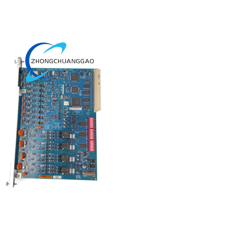
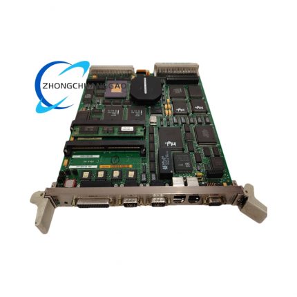
- Single-width horizontal rack plug-in structure matching CTI 2500 series backplane mechanical standard
- Front panel printed channel identification legend and DIP switch configuration access cover
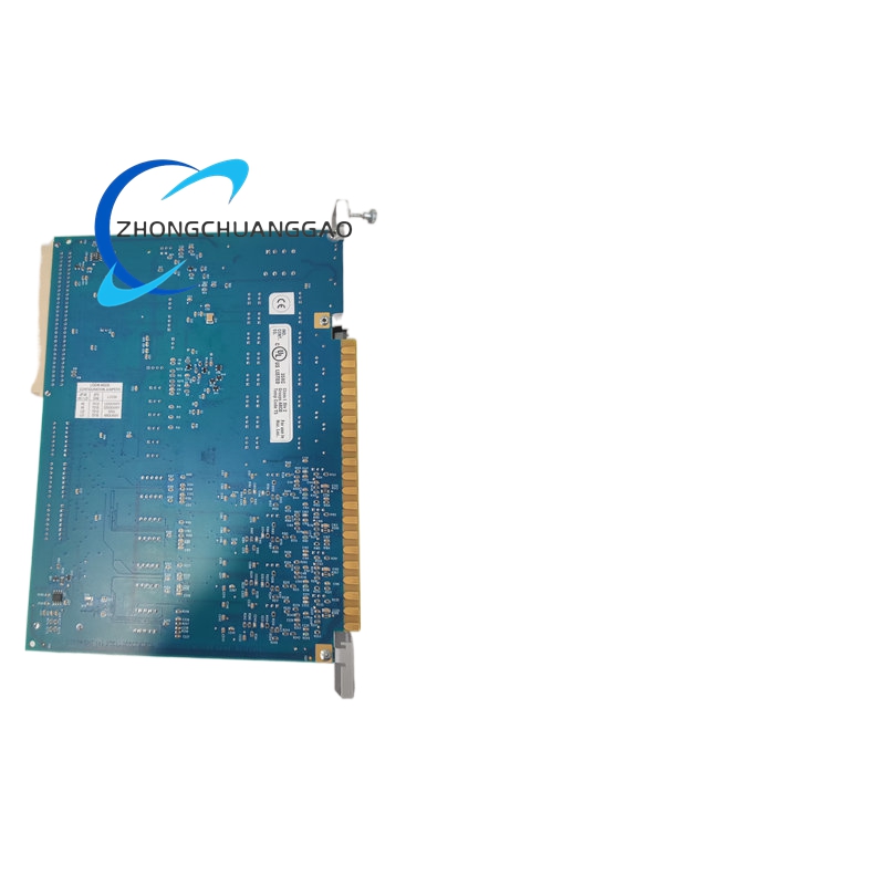
- Rear detachable terminal connector interface for simplified field wiring disconnection during module replacement
- Internal segmented PCB layout: Input isolation zone, output isolation zone, backplane communication interface zone
- Embedded electromagnetic shielding foil to suppress industrial variable frequency drive interference
- Front panel integrated status LED indicators for power supply, bus communication and channel fault alarm
Working Principle
- Field analog sensor signals enter isolated input circuits via detachable terminal connector; isolation transformers separate field ground potential from PLC backplane ground
- Multiplexer circuit sequentially routes each analog input signal to 12-bit ADC converter for digital value sampling
- Digital signal data transmits to backplane bus interface chip and uploads to Siemens 505 PLC CPU memory register
- CPU calculated control output digital values download back to CTI-2501 module via rack backplane bus
- DAC converters convert digital setpoints to analog voltage/current signals, passing through channel-to-channel isolation circuits before output to field actuators
- Onboard fault detection circuit continuously monitors channel short-circuit, overrange and power supply anomalies, transmitting diagnostic status to PLC program logic via backplane data registers
Advantage Highlights
- Drop-in replacement for legacy Siemens analog I/O modules eliminates costly field wiring rework during system upgrade
- Dual-stage 1500 V isolation (channel-to-backplane + channel-to-channel) delivers superior noise suppression in heavy industrial environments
- Per-channel independent signal range configuration supports mixed sensor types on single module hardware
- Ultra-fast 6 ms full-channel refresh cycle suitable for high-dynamics flow, pressure and temperature closed-loop control
- Hardware short-circuit protection on all output channels prevents permanent module failure from field wiring faults
- Wide -20 °C to +70 °C operating temperature range enables installation in unheated outdoor control cabinets
Applicable Industries
Oil & gas upstream process control, chemical batch manufacturing, power plant boiler auxiliary control, water/wastewater treatment plant automation, food and beverage processing lines, pharmaceutical batch production, metal machining CNC auxiliary signal acquisition
Installation Requirements
- Insert horizontally into CTI 2500 series or Siemens Simatic 505 standard rack backplane single-width slot
- Secure detachable 2500-40F terminal connector fully latched to rear module interface before wiring
- Maintain minimum 25 mm vertical air gap between adjacent rack modules for passive heat dissipation
- Separate analog signal wiring and high-current power cabling into isolated cable trays with minimum 10 cm separation distance
- Connect all signal cable shield screens to cabinet protective earth busbar at single grounding point only
- Rack backplane power supply must maintain regulated 24 V DC ±5% voltage tolerance
- DIP switch channel range configuration must be completed before connecting field sensor signal wiring
Usage Notes
- Verify DIP switch signal range configuration matches connected sensor specifications before energising module power
- Do not hot-swap module while rack backplane power supply remains energised to avoid backplane bus communication damage
- Limit analog output channel load resistance above minimum rated value to prevent output signal saturation
- Avoid routing analog signal cables parallel to high-frequency variable frequency drive power cables without shielding conduit
- Periodically inspect terminal connector screw torque to prevent loose wiring contact resistance drift
- Store spare modules within 5% – 95% non-condensing humidity range to avoid PCB trace corrosion
- Replace terminal connector if copper screw terminals exhibit oxidation or corrosion after long-term field operation




























Reviews
There are no reviews yet.