Technical Specifications
- Channel Count: 16 isolated digital input channels
- Input Signal Type: Sink/Source compatible 24VDC discrete field signals
- Input Threshold Voltage: Logic HIGH ≥ 18VDC; Logic LOW ≤ 5VDC
- Isolation Rating: 2000 VAC channel-to-backplane galvanic isolation
- Input Debounce Time: Software configurable 1ms / 5ms / 10ms / 20ms / 50ms per channel
- Operating Supply Voltage: 24VDC nominal, range 20.4VDC – 28.8VDC
- Power Consumption: Max 3.0W full channel energized load
- Max Channel Input Current: 8mA DC per single input channel
- EMC Compliance: IEC 61000-6-2, IEC 61000-6-3 Class A industrial standard
- Certifications: CE, UL 508, CSA C22.2 No.142
Functional Features
- Bidirectional sink/source input compatibility matches NPN and PNP field proximity sensors without wiring modification
- Per-channel software adjustable signal debounce filter eliminates contact bounce interference from mechanical limit switches
- Individual open-circuit fault detection for broken field wiring with dedicated fault flag transmission to controller
- Hot-swap compatible for all standard and redundant C200 control racks
- Separate LED status indicator for each input channel, global power and module fault diagnostic LED
- On-board non-volatile memory stores debounce timing and input polarity configuration parameters
- Supports safety interlock signal latching logic for emergency stop feedback monitoring
- Full channel overvoltage transient suppression circuits integrated at signal input terminals
Performance Parameters
- Input Circuit Response Speed: Maximum 0.8ms raw signal capture before debounce filtering
- Operating Ambient Temperature Range: 0°C to +60°C operational; -40°C to +85°C storage
- Relative Humidity Tolerance: 5% – 95% non-condensing
- Vibration Resistance: 10–150Hz, 1g sinusoidal vibration per IEC 60068-2-6
- Channel-to-Channel Crosstalk Attenuation: Min 60dB at industrial switching frequency bandwidth
Material Composition
- Main Circuit PCB: FR-4 flame-retardant fiberglass PCB with lead-free tin plating
- Terminal Block Housing: Reinforced PA66 glass-filled nylon, UL94 V-0 fire rating
- Module Chassis Frame: Cold rolled steel with black electrostatic anti-corrosion coating
- Connector Pins: Copper alloy with gold plating (1.0μm thickness)
- Electronic Components: Wide-temperature optocoupler isolation chips, ceramic surge suppression capacitors, current-limiting precision resistors
Structural Characteristics
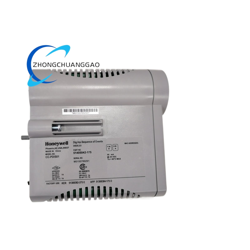
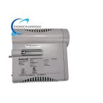
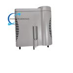
- Standard single-width rack form factor, dimension: 22.5mm (W) × 130mm (H) × 135mm (D)
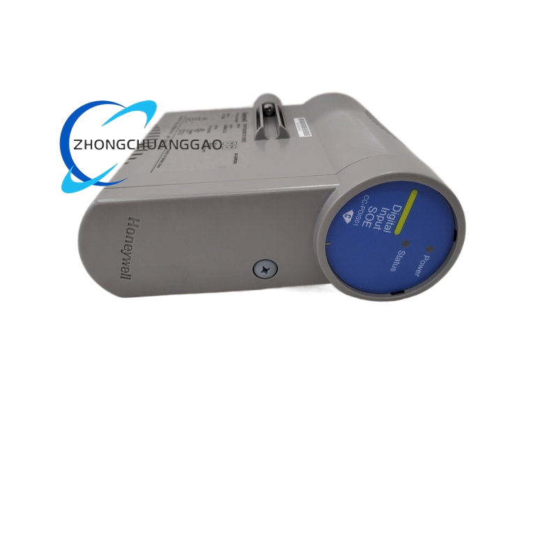
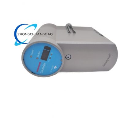
- Front panel integrated 16-channel LED array, global power green LED, module fault red LED
- Rear edge gold-plated connector for C200 proprietary backplane communication bus
- Removable screw-type terminal block containing 16 signal channel pairs and common ground shielding terminals
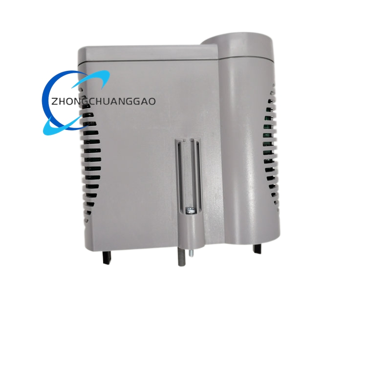
- Spring anti-vibration locking latch for stable rack slot fixation
Working Principle
Field 24VDC discrete contact signals transmit to front terminal block, pass through current-limiting resistors and surge suppression components before entering channel-specific optocoupler isolation circuits. Optocouplers fully separate field-side wiring circuits from controller backplane to eliminate ground loop interference. Isolated digital logic signals feed to on-board channel signal sampling circuits; software-configurable debounce filters suppress mechanical contact bounce noise. Sampled binary channel status data is buffered and transmitted via backplane bus to CC-PCNT01/CC-PCNT02 controller modules. The on-board microprocessor continuously monitors channel input voltage levels; any sustained voltage loss indicating broken field wiring triggers a fault flag and illuminates corresponding channel LED warning indicator. All channel configuration parameters are stored permanently within local non-volatile flash memory independent of rack power supply.
Advantage Highlights
- 16-channel high-density layout minimizes total rack space occupation for large-scale discrete signal collection
- Universal sink/source input design eliminates need for separate input module types for different sensor transistor polarities
- Adjustable per-channel debounce timing adapts to mechanical switches, solid-state sensors and high-speed pulse feedback signals
- Integrated optocoupler isolation prevents industrial field voltage surges from damaging central controller hardware
- Hot-swap maintenance capability avoids system shutdown during module replacement in redundant control architectures
- Embedded wire break detection reduces manual field wiring inspection workload during equipment troubleshooting
- Compact single-width form factor optimizes rack layout flexibility for mixed analog/digital I/O cabinet configurations
Applicable Industries
Food & beverage packaging lines, municipal wastewater pump station interlocks, thermal power auxiliary equipment status monitoring, mining conveyor safety switches, chemical plant valve position feedback, pharmaceutical batch equipment limit sensing
Installation Requirements
- Install exclusively inside Honeywell C200 standard control rack with matching CC series backplane
- Maintain minimum 12mm vertical clearance between adjacent modules for forced air convection cooling
- Cabinet internal cooling airflow rate minimum threshold: 0.6 m³/min per rack assembly
- Discrete field wiring must use shielded twisted pair cable with single-point shield grounding at cabinet earth bar
- Terminal block maximum allowable wire gauge: 16 AWG solid copper conductor
- Rack mounting environment continuous vibration amplitude limited below 0.5mm
- Separate low-voltage digital signal wiring from high-power AC motor drive cables with minimum 25cm physical separation distance
Operation & Maintenance Precautions
- Do not apply input voltage exceeding 30VDC to any channel terminal; overvoltage causes irreversible optocoupler breakdown
- Standard terminal screw tightening torque fixed at 0.7 N·m to avoid loose contact voltage drop and false input state signals
- Mechanical limit switch circuits require debounce timing setting above 10ms to eliminate bounce-induced false status triggers
- Anti-static wrist strap mandatory during module removal, wiring modification and replacement procedures
- Front panel surface cleaning restricted to dry anti-static microfiber cloth; liquid cleaning solvents are prohibited
- Verify standby redundant controller fully synchronized online status before performing hot-swap module maintenance
- Spare modules must be stored in sealed anti-static packaging with desiccant packs to prevent PCB moisture corrosion


























-430x430.jpg)

-430x430.jpg)

Reviews
There are no reviews yet.