Technical Specifications:
- Part Number: RH916YY
- Number of Channels: 8 channels (configurable as 4 differential + 4 single-ended, or 8 single-ended)
- Input Signal Types:
- TTL/CMOS: 0 to 5V DC, 0 to 24V DC
- Differential (RS-422): ±5V to ±15V
- Dry Contact (Switch Closure): Accepts dry contact inputs with internal pull-up
- Maximum Input Frequency: 10 MHz (10,000,000 Hz) per channel
- Counter Resolution: 32-bit (0 to 4,294,967,295 counts)
- Input Impedance: 100 kΩ minimum (single-ended); 10 kΩ (differential)
- Isolation: 250 VDC channel-to-channel isolation; 500 VDC channel-to-backplane isolation
- Debounce Time: Configurable from 1 ms to 100 ms
- Operating Temperature: 0°C to 60°C (32°F to 140°F)
Functional Features:
- Totalization (Cumulative Counting): Continuously accumulates pulse counts — used for batch totalization and energy measurement
- Frequency Measurement: Measures pulses per second — used for flow rate calculation
- Period Measurement: Measures time between pulses — used for speed measurement
- Quadrature Decoding: Supports A/B phase quadrature encoder inputs for direction-sensitive counting
- High-Speed Gating: Counts pulses during a configurable gate time window
- Alarm on Count: Generates alarm when count reaches preset high or low threshold
- Front Panel LEDs: Per-channel activity indicators and module status LEDs
Performance Parameters:
- Counting Accuracy: ±1 count at frequencies up to 1 MHz; ±0.01% at frequencies up to 10 MHz
- Minimum Pulse Width: 50 nanoseconds at 10 MHz
- Maximum Simultaneous Channels Active: All 8 channels can count simultaneously at full speed
- Scan Update Rate: Count values updated to processor every controller scan cycle (50–500 ms)
- Latency: Less than 1 ms from pulse arrival to count register update
Material Composition:
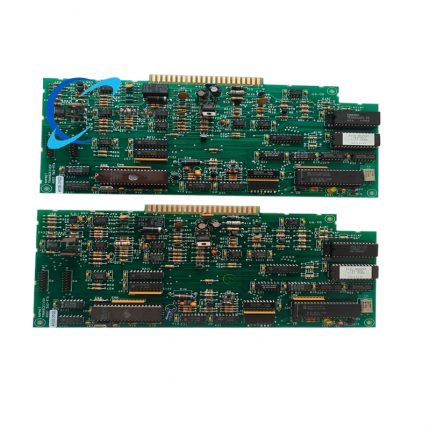
- PCB: Multi-layer FR-4 with gold-plated edge connectors
- Input Circuitry: Opto-isolated input stages with TVS diode surge protection
- Enclosure: Steel with zinc-nickel plating
- Connectors: Screw-terminal blocks for field wiring (wire gauge 12–26 AWG)
Structural Characteristics:
- Form Factor: Standard Eurocard module (160 mm × 233 mm)
- Mounting: Horizontal rack mount
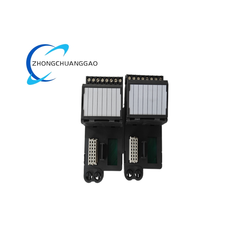
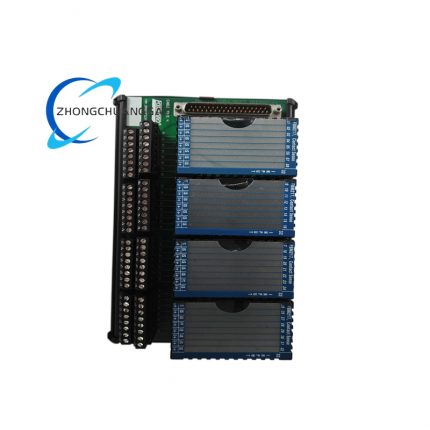
- Field Wiring: Screw-terminal connectors on front panel — 8 channels, 2 wires per channel (signal + common)
- Weight: Approximately 0.6 kg (1.32 lbs)
Working Principle:
Incoming pulses from field devices are conditioned (level-shifted, filtered, debounced) by the input circuitry. A hardware counter increments on each valid pulse edge (rising, falling, or both — configurable). The 32-bit counter value is latched at the end of each controller scan cycle and transferred to the FBM219 processor via the backplane. The processor reads the latched count, calculates frequency (counts/scan interval), totalizes, and applies engineering units scaling. Quadrature inputs use A/B phase comparison to determine count direction (up/down).
Advantages & Highlights:
- 10 MHz maximum frequency — handles the fastest turbine and encoder signals
- 32-bit counter — eliminates rollover concerns for long-duration totalization
- 8 independent channels — reduces module count in multi-meter installations
- 250 VDC inter-channel isolation — prevents crosstalk between channels
- Quadrature decoding — direct encoder connection without external hardware
Applicable Industries:
- Oil and Gas (custody transfer flow measurement, turbine metering)
- Power Generation (turbine speed measurement, generator pulse counting)
- Chemical (batch totalization, conveyor counting)
- Mining (conveyor belt speed, ore counting)
- Pulp and Paper (web counting, roll measurement)
Installation Requirements:
- Install in any available chassis slot
- Use shielded cable for high-frequency signals — connect shield to chassis ground at ONE end only
- For differential inputs, use twisted-pair cable with proper termination
- Dry contact inputs require external pull-up — module provides internal 24V pull-up (configurable)
- Maximum cable length: 30 meters (100 feet) for 10 MHz signals; 300 meters (1,000 feet) for signals below 100 kHz
Usage Precautions:
- Do not exceed 10 MHz input frequency — counts will be lost above this limit
- Do not apply voltage exceeding 30V DC to any input — will damage input circuitry
- Ensure proper grounding — floating inputs can cause erratic counting
- Configure debounce time appropriately — too short causes false counts from contact bounce



























Reviews
There are no reviews yet.