Technical Specifications Model: ACC-24E2A (Accessory 24E2A, part number 603398-xUxx) Manufacturer: Delta Tau Data Systems, Inc. (Chatsworth, CA) Configuration: 2-axis per board; 4-axis via two connected boards Command Output Modes:
- ±10 V analog velocity command
- ±10 V analog torque command
- Sinusoidal ±10 V phase current command
- Pulse and direction output for stepper systems or MLDT Encoder Input per Channel: 3-wire (A/B/Z), differential or single-ended 1 Vpp Sinusoidal Encoder: 4096× interpolator SSI Encoder Interface: up to 8 channels 16-bit A/D Converter Inputs: up to four per card Flag I/O per Channel: 8 input flags, 2 output flags Flag Input Voltage: 5 V to 24 V Encoder Loss Detection: dedicated circuit per channel Backplane Interface: UMAC expansion bus / MACRO Station expansion port Compatible CPUs: any UMAC CPU or MACRO Station CPU Maximum Boards per UMAC: up to 8 ACC-24E2A boards (32 channels total) MACRO Station Capacity: 16-axis MACRO CPU supports 4 ACC-24E2x cards; 8-axis MACRO CPU supports 2 cards Operating Temperature: 0 to +45 °C Storage Temperature: -25 to +70 °C Humidity: 10% to 95% non-condensing Dimensions (without Option 1A): 16.256 cm length × 10 cm height × 2.03 cm width Dimensions (with Option 1A): length extended per option Certification: CE, Declaration of Conformity per applicable standards
Functional Features Four analog servo channels (two boards) deliver ±10 V precision command outputs for velocity, torque, or sinusoidal current control. 16-bit A/D converter inputs accept analog feedback signals such as torque sensors, strain gauges, or auxiliary position sensors. 4096× interpolation for 1 Vpp sinusoidal encoders provides sub-micron position resolution. SSI encoder interface supports absolute encoders up to 8 channels. Eight input flags and two output flags per channel handle limit switches, home references, amplifier enable, and fault signals. Encoder loss detection triggers a fault state on feedback failure. Up to eight boards in one UMAC chassis expand the system to 32 servo channels.
Application Scenarios High-precision multi-axis motion control in CNC machining centers, multi-axis robotic manipulators, semiconductor wafer handling equipment, flat-panel display manufacturing, laser positioning systems, coordinate measuring machines, and aerospace test rigs. The 4-axis configuration suits gantry systems, SCARA robots, and synchronized multi-axis machinery requiring analog servo command interfaces.
Performance Parameters Analog output resolution: 16-bit (±10 V range) Analog output accuracy: within ±1 mV of full scale A/D converter resolution: 16-bit, up to 4 inputs per board Encoder interpolation: 4096× for 1 Vpp sinusoidal SSI channels: up to 8 per board Flag inputs: 8 per channel, 5 to 24 V Flag outputs: 2 per channel, open-collector Maximum axes per UMAC: 32 (8 boards × 4 axes via paired configuration) Servo update rate: synchronized to UMAC Turbo servo cycle (sub-100 µs capability)
Material Composition FR-4 glass-epoxy multi-layer PCB with solder mask and component silkscreen. Gold-plated backplane connector and DB-15 / terminal-block front-panel connectors. Aluminum front panel with engraved labels. High-precision 16-bit DAC and ADC integrated circuits. Operational amplifiers for analog signal conditioning. Optocouplers for flag I/O isolation. Steel standoffs and mounting hardware.
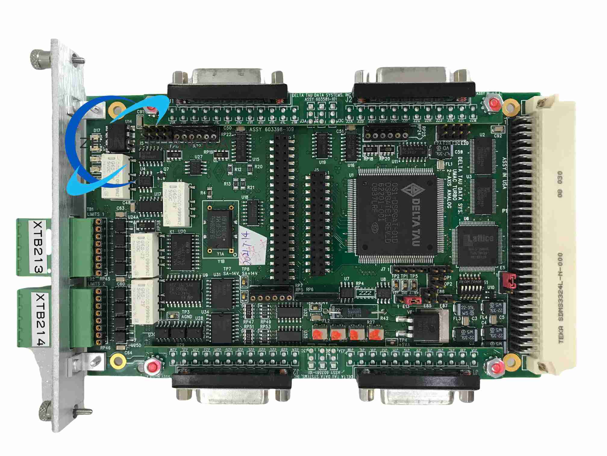
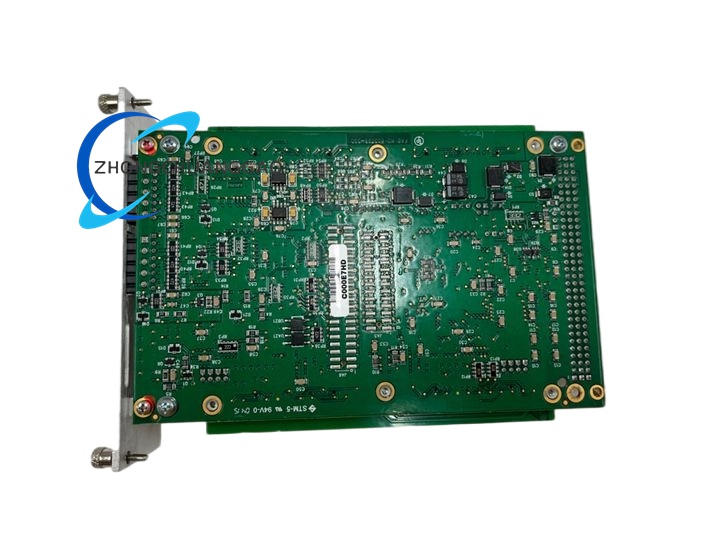
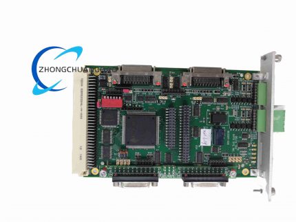
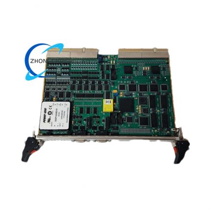
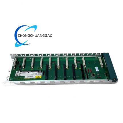
Structural Features 3U Eurocard plug-in board for the UMAC rack. Front panel provides DB-15 connectors or terminal blocks for two channels of analog output, encoder input, and flag I/O, plus status LEDs and a retaining screw. A 4-axis system uses two ACC-24E2A boards connected via an internal ribbon or expansion connector. Option 1A extends the board length for additional front-panel I/O. The rear connector mates with the UMAC backplane for power and UBUS communication. Internal analog and digital ground planes are separated for noise immunity.
Working Principle The UMAC Turbo or MACRO Station CPU executes motion control algorithms and writes 16-bit digital command values to the ACC-24E2A over the UBUS backplane. A high-resolution DAC converts each command into a ±10 V analog voltage for velocity, torque, or sinusoidal current output to the servo amplifier. Encoder feedback (quadrature, 1 Vpp sinusoidal, or SSI absolute) is received, interpolated, and counted by the board’s interface circuitry, then read back by the CPU to close the position and velocity loops. The 16-bit A/D converter captures auxiliary analog signals for force control or sensor feedback. Flag I/O is monitored and controlled through memory-mapped registers. All control intelligence resides in the host CPU; the board provides only signal conversion and buffering.
Installation Requirements Power off the UMAC chassis before installation. Insert the first ACC-24E2A into an available 3U slot and the second board into an adjacent slot for 4-axis operation; connect the inter-board ribbon cable if required. Tighten all front-panel retaining screws. Connect analog command cables, encoder cables, and flag I/O cables to the front-panel connectors using shielded twisted-pair wire. Configure each channel’s output mode (velocity, torque, sinusoidal current, or pulse/direction), encoder type, and flag voltage in the UMAC engineering software. Verify the CPU supports the total axis count (4 axes requires at least a 4-axis-capable UMAC or MACRO Station). Ensure ambient temperature remains within 0 to +45 °C and humidity is non-condensing.
Usage Precautions Do not install or remove boards while chassis power is on. Use shielded cable for all analog command and encoder signals; ground shields at the controller end only. Keep analog command wiring separated from motor power cables to prevent noise coupling. Verify analog output polarity and zero offset before enabling servo drives to prevent runaway motion. Set flag input voltage to match the connected sensor supply (5 V or 24 V). Do not connect encoder signals exceeding the rated input voltage. Calibrate analog output zero and gain after installation for optimal precision. Ensure encoder loss detection is enabled in the control configuration to trigger a safe stop on feedback failure.



























Reviews
There are no reviews yet.