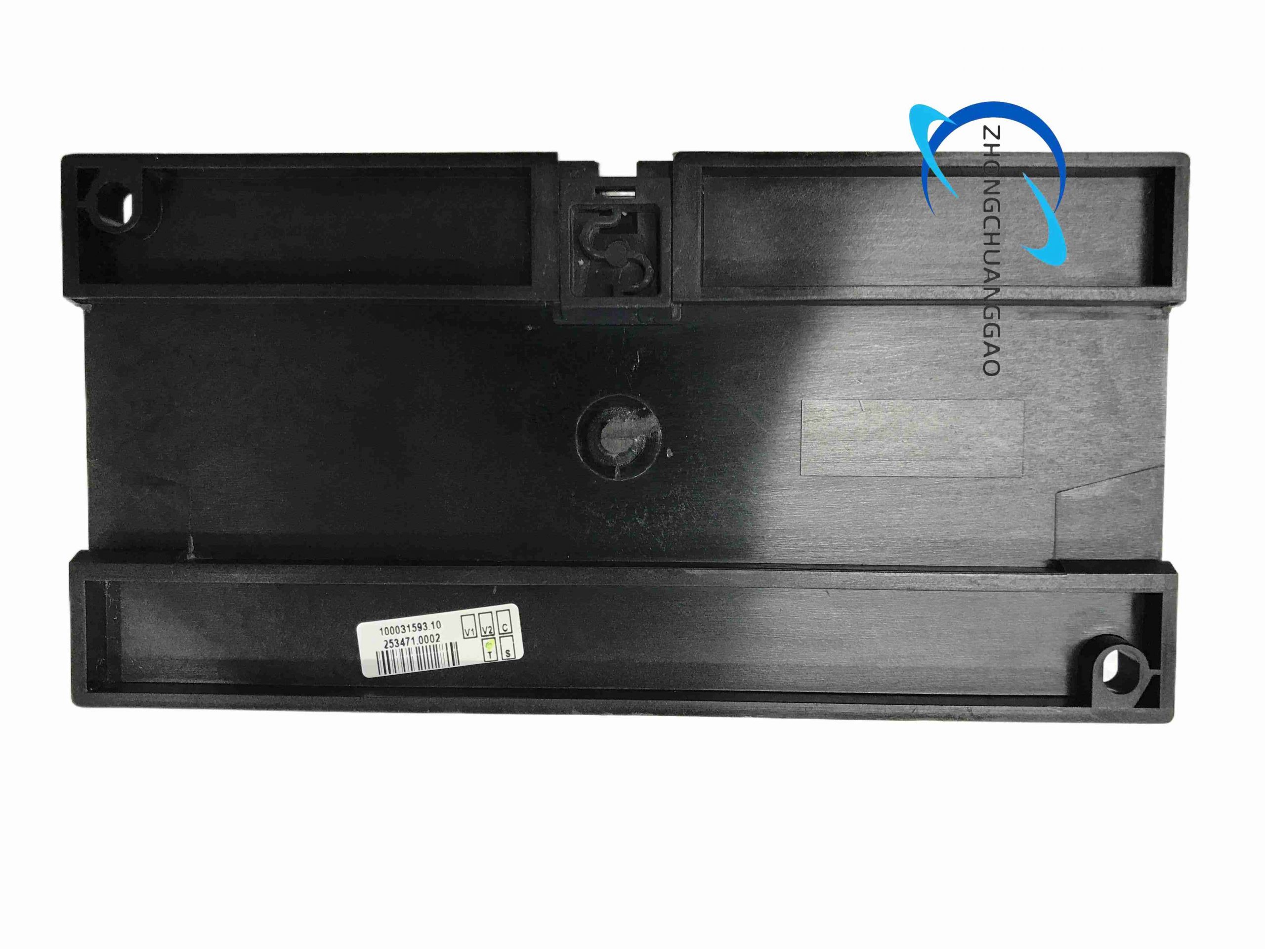
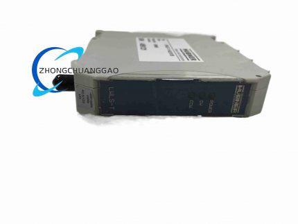
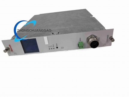
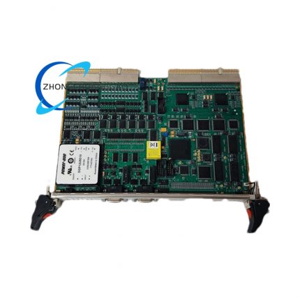
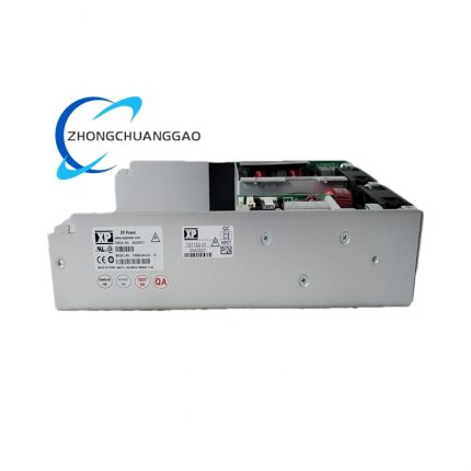
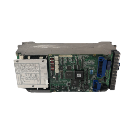
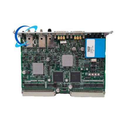
Technical Specifications Product type load sharing and speed control unit. Voltage measurement range approximately 57.7-690 V AC depending on version. Current measurement 0.3-5.0 A AC via current transformers, with 4x continuous, 20x for 10 s and 80x for 1 s overload capacity in stated distributor data. Frequency range 40-70 Hz. Speed sensing through magnetic pickup. Auxiliary supply data varies by source; distributor listings state 12-48 V DC logic supply, while installation data also reference low VA auxiliary consumption, so the exact supplied unit variant must be confirmed. Analog paralleling lines FS frequency and PS power, each -5 to +5 V deviation. Reference input 0.5-5 V DC for local power control. Relay outputs for speed increase and decrease, plus additional status/unload relays. Mounting 35 mm DIN rail or base mounting. Ingress IP20. Operating temperature -25 °C to 70 °C. Weight approximately 0.75 kg.
Functional Features
Isochronous and droop speed control, active kW load sharing across parallel gensets, actuator control for engine governor, AVR/excitation support functions, over/under frequency, over/under voltage, overcurrent and overpower protection, self-monitoring microcontroller, status LEDs, and optional communication cards for Modbus RTU or J1939 depending on fitted module.
Application Scenarios
Diesel generator panels, emergency marine power, offshore platforms, prime power microgrids, peak-shaving genset paralleling, rental power stations and industrial backup systems requiring stable frequency and proportional load division.
Performance Parameters
Frequency control 40-70 Hz working range, 50/60 Hz selectable nominal. Voltage measurement up to 690 V AC version-dependent. Current input 0.3-5 A CT secondary. FS and PS analog lines -5 to +5 V. Speed relay contacts rated up to 250 V AC or 24 V DC at 8 A resistive in cited distributor data. Isolation approximately 3250 V between measuring, current, relay, analog and supply circuits.
Material Composition
Plastic IP20 enclosure, PCB with measurement and DSP/ microcontroller circuits, relay outputs, screw terminals, DIN rail clip or base-mount brackets, and optional communication daughter card.
Structural Characteristics
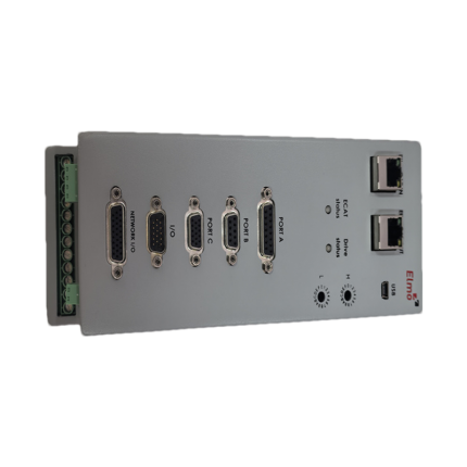
Compact DIN-rail module with terminal rows for voltage, current, speed sensor, actuator, paralleling lines and relays. Front LEDs for power, voltage presence and active sharing status. Keypad or external display compatibility depends on system configuration; some LSU configurations use separate HMI/control panels.
Working Principle
The unit measures generator voltage, current and frequency and receives engine speed from the magnetic pickup. It compares actual frequency and active power with the reference and with FS/PS signals from other units. The controller adjusts the speed actuator to maintain isochronous frequency or droop characteristic and adjusts load-share output so parallel gensets divide kW proportionally. Protection logic trips or alarms on abnormal frequency, voltage, current or power.
Installation Requirements
Mount vertically on 35 mm DIN rail or by base screws with adequate spacing for ventilation. Connect phase voltage to the Un terminals per wiring diagram, CT secondaries to current terminals with proper polarity, and MPU speed sensor to the tach input. Wire FS and PS lines common to all parallel units. Connect actuator and AVR control outputs through appropriately rated intermediate relays where required. Provide stabilized DC auxiliary supply according to the unit nameplate.
Usage Precautions
Confirm voltage and CT ratios before energizing. Do not exceed 110% of nominal measured values on voltage or current inputs. Set 50/60 Hz, droop percentage, proportional band and integral time to match the engine governor. Test unload, paralleling and protection functions during commissioning. Maintain IP20 enclosure inside a switchgear cubicle; do not expose to direct spray, condensation or conductive dust.
Reviews
There are no reviews yet.