Technical & Performance Specifications
- Nominal Coil Operating Voltage: 12 V DC vehicle electrical system
- Max Continuous Contact Current Rating: 85 A DC
- 30 Second Surge Overload Current: 250 A DC
- Coil Pull-In Voltage Threshold: Max 7.8 V DC (12 V nominal)
- Coil Release Voltage Threshold: Min 1.2 V DC (12 V nominal)
- Contact Construction: Silver alloy high-current switching contacts
- Contact Dielectric Strength: 500 V RMS isolation between coil circuit and power contact circuit
- Insulation Resistance: Minimum 100 MΩ between coil and contact terminals
- Mechanical Service Life: 10,000,000 switching cycles
- Electrical Service Life (Full Rated Load): 100,000 switching cycles
- Operating Ambient Temperature Range: -40°C ~ +85°C
- Protection Rating: IP40 dust-resistant sealed housing
- Termination Type: Tin-plated copper bolt terminals for 6–16 AWG vehicle wiring
- Unit Weight: 280 g
- Certifications: SAE J1171 marine ignition protection, CE, RoHS compliant
Function Features
- Automatic voltage-sensing logic detects alternator charging voltage to engage parallel battery connection
- Passive isolation mode during engine shutdown prevents secondary battery draining into primary starting battery
- No external control wiring required; self-contained voltage detection circuit eliminates auxiliary switches
- Integrated transient voltage suppression diode protects internal coil circuitry from vehicle alternator voltage spikes
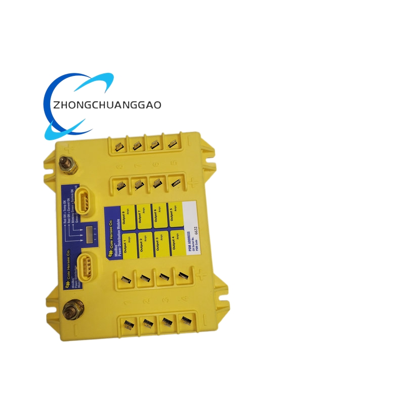
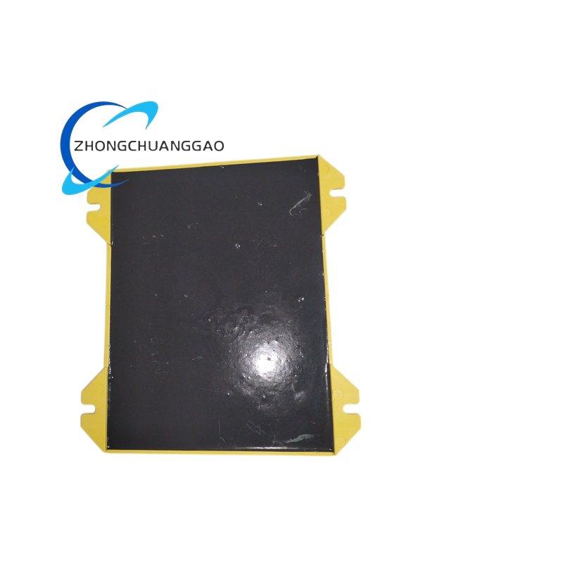
- Compact bolt-mount housing with integrated L-shaped mounting bracket for chassis or battery compartment installation
- Sealed internal coil assembly eliminates moisture corrosion damage in under-hood vehicle environments
Working Principle
An internal precision voltage comparator continuously monitors primary battery terminal potential. When alternator output voltage rises above the factory-set charging threshold, the comparator energizes the electromagnetic coil, pulling the heavy-duty silver alloy contact bridge closed to electrically link primary and secondary battery banks for unified charging. When engine operation ceases and system voltage drops below release threshold, coil de-energizes, contact bridge opens to fully isolate battery banks, blocking parasitic current flow between battery circuits to preserve starting battery charge for subsequent engine cranking.
Material & Structural Composition
- Outer housing: High-impact black glass-filled nylon sealed enclosure with ultrasonic welded seams
- Electromagnetic coil: Copper magnet wire wound on laminated silicon steel core, epoxy resin potted for moisture resistance
- Power contacts: Silver cadmium alloy composite contact material with anti-arcing surface treatment
- Mounting hardware: Galvanized steel L-bracket with pre-drilled mounting holes, corrosion-resistant zinc-plated terminal bolts
- Internal circuit board: FR4 PCB with surface-mount voltage sensing and surge suppression components
Advantage Highlights
- Eliminates manual battery disconnect switches to reduce operator error and wiring complexity
- Prevents dead starting batteries caused by long-term auxiliary equipment standby power draw
- Sealed IP40 construction withstands vibration, dust, humidity and temperature cycling in vehicle under-hood compartments
- High continuous current rating supports heavy auxiliary loads including hydraulic pumps, refrigeration units and lighting banks
- Integrated surge protection eliminates premature coil failure from vehicle electrical transient spikes
- No external control power required; fully autonomous operation with zero operator intervention
Applicable Industries
Commercial delivery trucks, construction excavators/loaders, agricultural tractors, marine yachts and work boats, RV recreational vehicles, military tactical ground vehicles, mining underground equipment
Installation Requirements
- Mounting surface: Rigid flat metal chassis panel with minimum 3 mm thickness, secured via supplied M5 mounting hardware
- Wiring standard: 8 AWG minimum stranded copper automotive cable for battery power terminals, torque terminal bolts to 4 N·m factory specified value
- Environmental restriction: Do not install in direct contact with exhaust manifold or other heat sources exceeding 85°C surface temperature
- Terminal separation: Maintain minimum 20 mm clearance between positive battery terminals and chassis ground to prevent accidental short circuit
Operation & Maintenance Notes
- Torque recheck all terminal bolt connections every 6 months to eliminate resistance heating from loose wiring
- Inspect housing ultrasonic weld seams for cracking after heavy vehicle vibration exposure
- Replace unit immediately if contact arcing discoloration is visible on terminal lugs
- Do not modify internal sealed housing potting compound; disassembly voids all factory certification and warranty
- Verify coil voltage threshold function with multimeter after battery replacement or alternator service




























Reviews
There are no reviews yet.