Technical Specifications
Manufacturer: ALSTOM, currently supported under GE Grid Solutions/GE Vernova documentation.
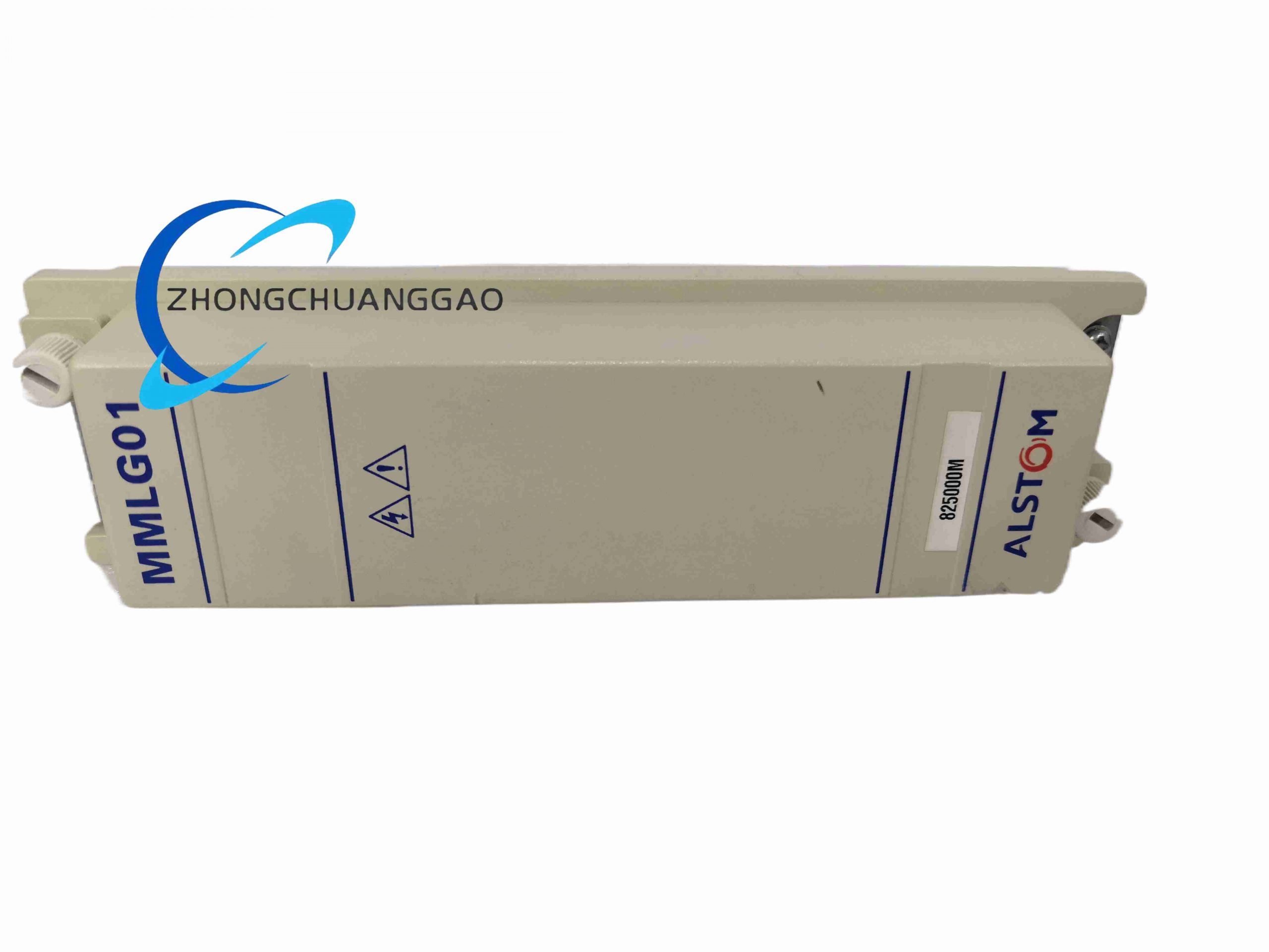
Model: MMLG01.
Product type: plug-in protective-relay test block.
Circuits: 14 circuits, each terminated at separate rear terminal pairs in standard MMLG data.
Compatible test plug: MMLB01 multi-finger plug in Midos-system documentation.
Rated voltage: 300 V AC/DC in standard industrial test-block listings.
Rated current: 20 A continuous in standard listings; CT-secondary ratings vary in abbreviated sources.
Short-circuit safety: CT circuits are automatically shorted by internal contacts according to the block sequence when the test plug is operated.
Insulation and standards: IEC 60255 compliance in protection-relay listings.
Mounting: panel flush mounting or relay-panel mounting according to configuration.
Rear termination: screw terminals for CT, VT, relay and test wiring.
Operating temperature: approximately -25°C to +55°C in general test-block listings.
System compatibility: ALSTOM Midos relay systems and MiCOM protection ranges according to relay documentation.
Functional Features
Make-before-break contact sequence prevents CT open-circuit during testing.
Fourteen independent circuits allow current, voltage, signal and auxiliary contacts to be isolated individually.
Rear terminal pairs simplify permanent wiring and test-set connection.
Panel-mounted design places test access at the relay front.
Compatibility with MMLB01 plug enables standardized secondary injection.
Mechanical isolation provides a physical air-gap alternative to software-only testing.
Application Scenarios
Substation protection panels, generator protection, transformer differential schemes, feeder and motor protection, transmission and distribution relay maintenance, industrial power stations, retrofit projects from electromechanical relays to digital IEDs, and relay training benches.
Performance Parameters
Each circuit maintains rated voltage and current within the declared limits while the relay remains in normal service. During test-plug insertion, the internal contacts open the relay connection and present the circuit to the test set while CT paths remain shorted. The block sustains repeated insertion cycles without degrading contact resistance when maintained according to the service schedule.
Material Composition
Molded insulating housing, silver-plated contact elements in low-resistance listings, spring mechanisms for automatic shorting, brass or tinned screw terminals, panel mounting hardware, identification labels.
Structural Characteristics
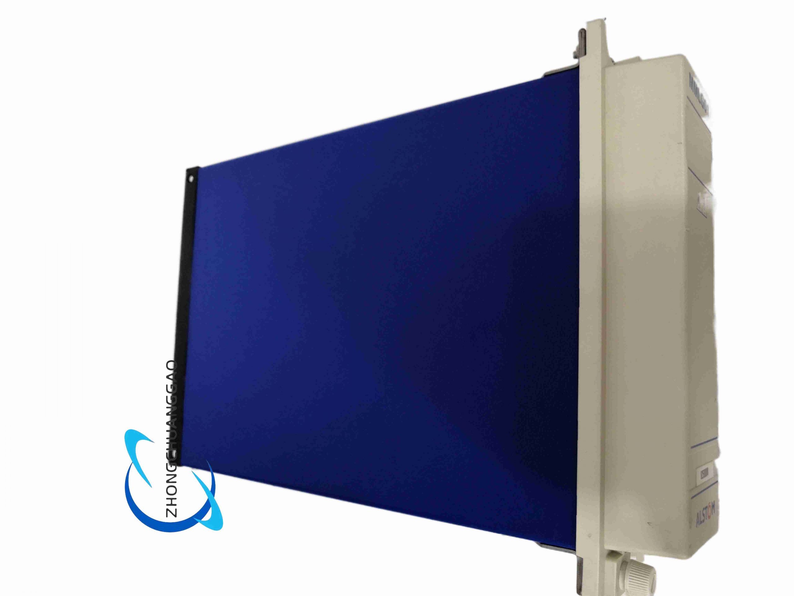
Front test-block face with plug apertures, 14 internal contact pairs, rear terminal rows, spring-loaded shorting links for CT circuits, panel flange and fixing points, compatible pocket for MMLB01 plug.
Working Principle
In normal service, internal contacts close each circuit between the relay and the CT/VT or auxiliary wiring. When the test plug is inserted, the plug actuators operate the contact sequence so the relay terminals are disconnected and the test terminals are connected. CT contacts are shorted before the measuring circuit is opened, preventing dangerous open-circuit voltage. Voltage and signal circuits are isolated according to the same mechanical sequence, allowing secondary injection without removing panel wires.
Installation Requirements
Mount the block on the relay panel with access aligned to the protected equipment. Wire CT secondaries, VT secondaries and relay leads to the designated rear terminals using the approved schematic. Verify terminal torque, contact identification and plug orientation. Install MMLB01 or the specified test plug nearby. Maintain clearance for plug insertion and label each circuit according to the protection single-line diagram.
Usage Precautions
Never test CT circuits without confirming the automatic shorting function. Verify contact sequence during planned outages before live relay work. Use only compatible ALSTOM/GE plugs and replacement blocks with identical pole count and rating. Inspect contacts for overheating, oxidation and spring fatigue. Follow IEC 60255 and site electrical-safety rules for relay testing. Do not exceed 300 V and the declared current rating for the installed block configuration.


























-430x430.jpg)
-430x430.jpg)
-430x430.jpg)

Reviews
There are no reviews yet.