Technical Specifications
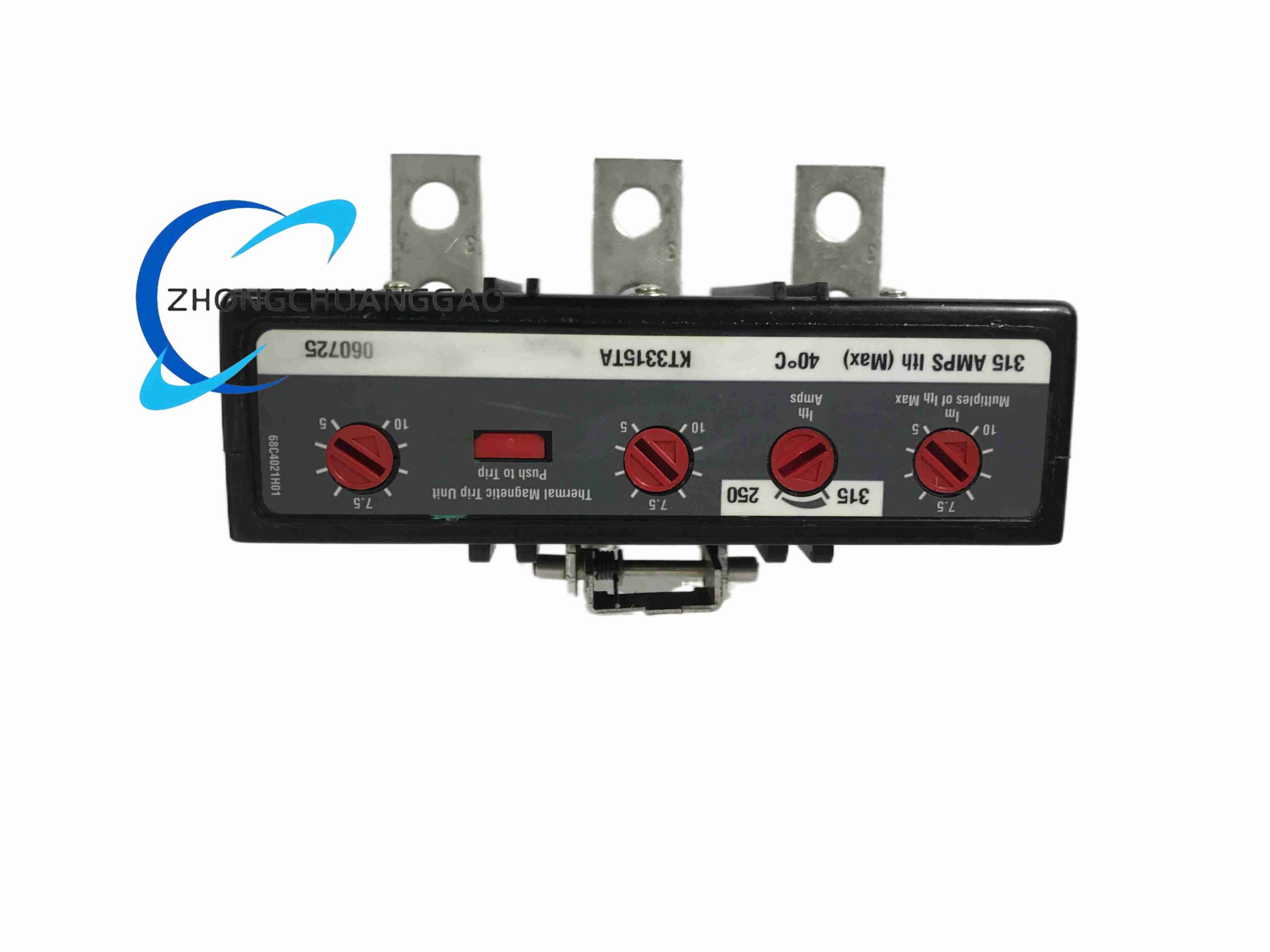
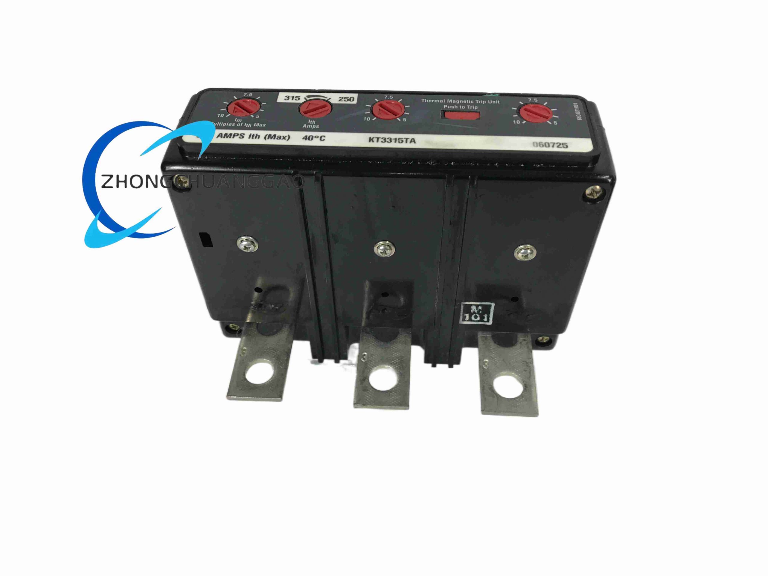
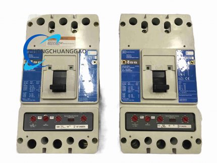
Continuous current rating 315 A. Pole count 3. Adjustable thermal range 250 A to 315 A. Adjustable magnetic trip range 1575 A to 3150 A. Maximum voltage class 600 V AC. Trip type adjustable thermal-magnetic. Frame type K/Series C per distributor listings; some distributors list J-K frame variant data. Standards basis UL 489 and CSA C22.2 No. 5 for comparable Series C trip elements; selected listings show non-UL special calibration.
Function Features
Field-adjustable thermal threshold reduces nuisance tripping. Field-adjustable magnetic threshold matches available fault current and load starting peaks. Separate trip unit allows frame, terminals and accessories to be matched independently.
Structure Characteristics
Thermal section uses calibrated bimetal elements that bend with temperature rise. Magnetic section uses an armature or solenoid operated by instantaneous current. The unit mounts inside the breaker frame and interfaces with operating mechanism, contacts and arc chute assembly.
Working Principle
Sustained overload heats the bimetal; at the set thermal current the element deflects and releases the trip mechanism. High fault current produces a strong magnetic field in the magnetic section, immediately attracts the armature and opens the contacts. After clearing, the breaker must be manually reset once the fault is removed.
Installation Requirements
Install only into the compatible Eaton Series C frame and pole configuration. De-energize the switchboard before removal or fitting. Verify frame size, terminal kit, lug torque and clearance. Confirm thermal dial and magnetic dial settings before energization. Use qualified electrical personnel.
Usage Precautions
Do not exceed 315 A continuous rating or the frame voltage rating. Verify whether the specific unit is UL listed or special non-UL calibration before applying to a certified installation. Recalibrate or replace if the breaker has tripped repeatedly under fault conditions. Store in dry conditions and avoid mechanical shock to the trip calibration mechanism.
Eaton KW3400
Product Name
Eaton Series C KW molded-case circuit breaker, KW3400.
Product Introduction
KW3400 is a three-pole thermal-magnetic molded-case circuit breaker rated 400 A for industrial and commercial power distribution. It is used for main incoming protection, sub-feed protection, motor feeder protection and switchboard branch protection where high breaking capacity is required.
Technical Specifications
Rated current 400 A at 40 °C. Pole count 3. Voltage rating 690 V AC IEC, 50/60 Hz. Breaking capacity IEC: 85 kA at 220 V to 240 V AC, 45 kA at 380 V to 415 V AC, 20 kA at 660 V to 690 V AC, 10 kA at 250 V DC. Frame type KW/K-frame. Trip type thermal-magnetic. Terminals aluminum/copper standard pressure line and load terminals.
Function Features
High short-circuit breaking range across low and medium voltage bands. Thermal setting protects against sustained overload. Magnetic setting provides fast instantaneous interruption for short circuits. Standard pressure terminals accept Al/Cu conductors for panelboard and switchboard wiring.
Structure Characteristics
Molded insulating case encloses fixed and moving contacts, bimetal thermal element, instantaneous magnetic actuator, arc runners and arc chute. Operating handle, trip indicator and accessory cavities support auxiliary contacts, alarm contacts, shunt trip and undervoltage release.
Working Principle
Overload current heats the bimetal until mechanical trip occurs after a time inversely related to current magnitude. Short-circuit current generates a magnetic field that instantly actuates the trip armature, opening contacts and directing arc energy into the arc chute for quenching.
Installation Requirements
Mount in a certified panelboard, switchboard or enclosed structure with adequate ventilation and breaker rating. Use qualified electrician services. Select conductor size for 400 A continuous load and terminal temperature rating. Apply specified torque to Al/Cu line and load terminals. Verify system prospective fault current against the voltage-specific kAIC rating.
Usage Precautions
Do not apply beyond 690 V AC or 250 V DC IEC limits. Match breaking capacity to the installation fault level at each voltage band. Inspect contacts and mechanism after short-circuit interruption. Replace rather than reuse if internal arc damage is present. Keep accessory wiring separate from power terminals.



























Reviews
There are no reviews yet.