Technical & Electrical Specifications
- Rated Input Power: 20–28 VDC, ripple factor ≤10%, maximum power consumption 38 W
- Dielectric Withstand Voltage: 1500 VAC for 1 minute between power circuit, field circuit and protective ground
- Insulation Resistance: ≥10 MΩ under 500 VDC test voltage
- Max Inrush Current: 20 A instant peak
- Communication Medium: 24 AWG minimum shielded twisted pair cable, foil overall shielding mandatory
- Bus Protocol: Proprietary DirectLogic 405RS serial remote I/O synchronous communication protocol
- Operating Ambient Temperature: 0 °C to +60 °C
- Storage Temperature: -20 °C to +70 °C
- Relative Humidity Range: 5%–95% non-condensing
- Physical Dimension: 127 mm (W) × 102 mm (D) × 152 mm (H)
- Net Weight: 0.79 kg
- Tariff HS Code: 8537109060
Functional Features
- Two mutually isolated internal circuit zones: power conversion zone and serial communication signal processing zone
- Built-in run relay status feedback terminal for system fault diagnosis
- Hardware DIP switch address coding for multi-slave bus network differentiation, maximum support 32 slave nodes per D4-RM master
- Internal surge suppression circuit for 24VDC field power anti-interference
- Real-time channel fault indicator LED array for open-circuit and short-circuit quick troubleshooting
- Full compatibility with ZIPLink quick wiring terminal system for fast field wiring replacement
- Automatic signal gain calibration circuit eliminating bus transmission attenuation over 1000-meter cable length
Working Principle
24VDC industrial power input passes EMI filter and isolated switching power circuit to generate stable internal working voltage for communication chip and relay drive circuit. The serial transceiver chip converts parallel PLC I/O data frames into differential serial signals transmitted via shielded twisted pair to D4-RM master module. Bidirectional data exchange synchronizes on-site discrete input signal status and PLC output control commands. Internal run relay cuts off bus communication loop upon overvoltage or overcurrent fault to isolate field failure from main PLC CPU.
Material Composition
- Outer Housing: Flame-retardant ABS plastic, UL94-V0 fire rating
- Internal PCB Substrate: FR4 high-temperature resistant glass fiber board, SS-2 94V-0 flame retardant grade
- Heat Dissipation Component: Extruded aluminum integrated cooling fin
- Terminal Block: Nickel-plated copper conductive terminals with PA66 insulating base
- Communication Transformer: Ferrite core isolated signal transformer
Structural Characteristics
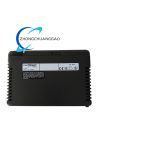
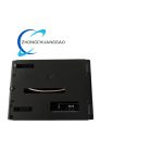
- Standard DIN 35 mm rail mounting structure, snap-lock fixed installation
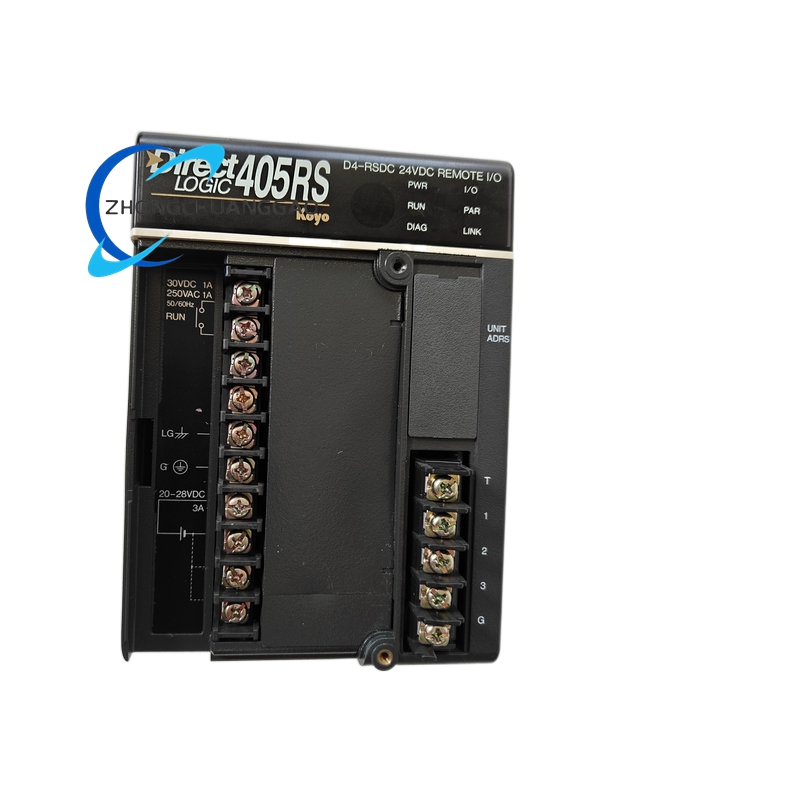
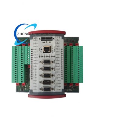
- Front panel centralized wiring terminal block layout, separate power terminal group and communication bus terminal group
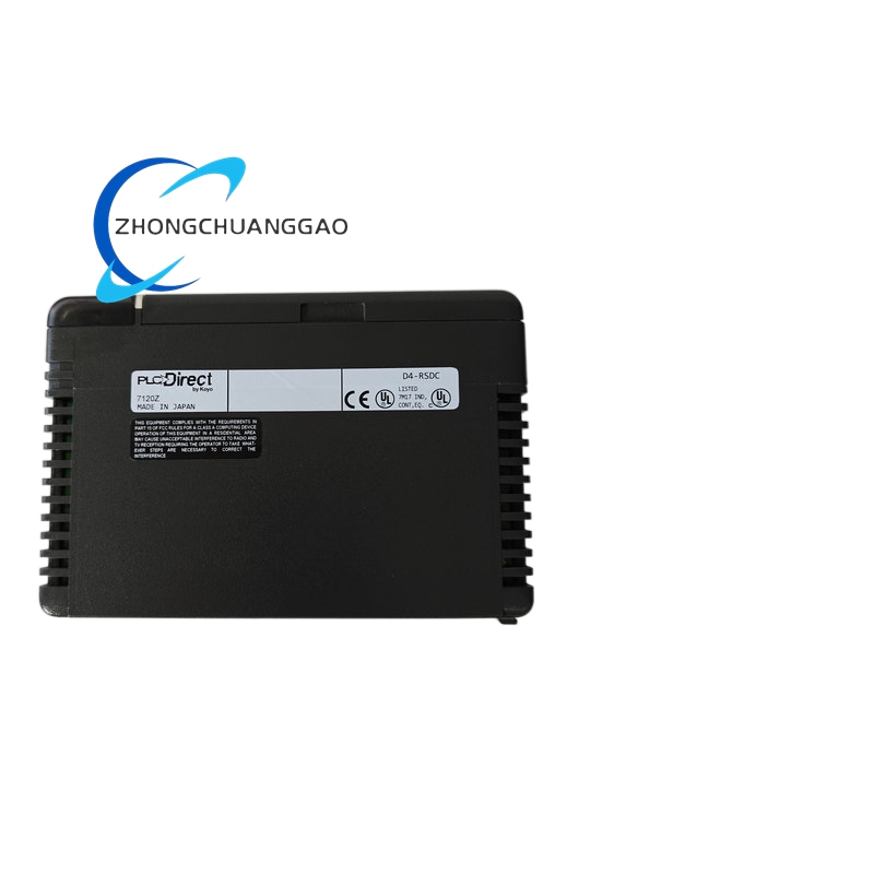
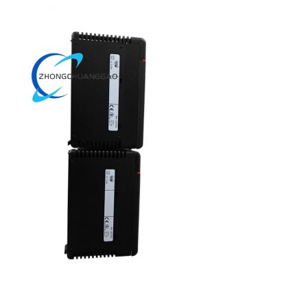
- Side vertical ventilation slotted heat dissipation channel for passive air cooling
- Top surface LED status indicator matrix including power, bus link, run relay and fault alarm lights
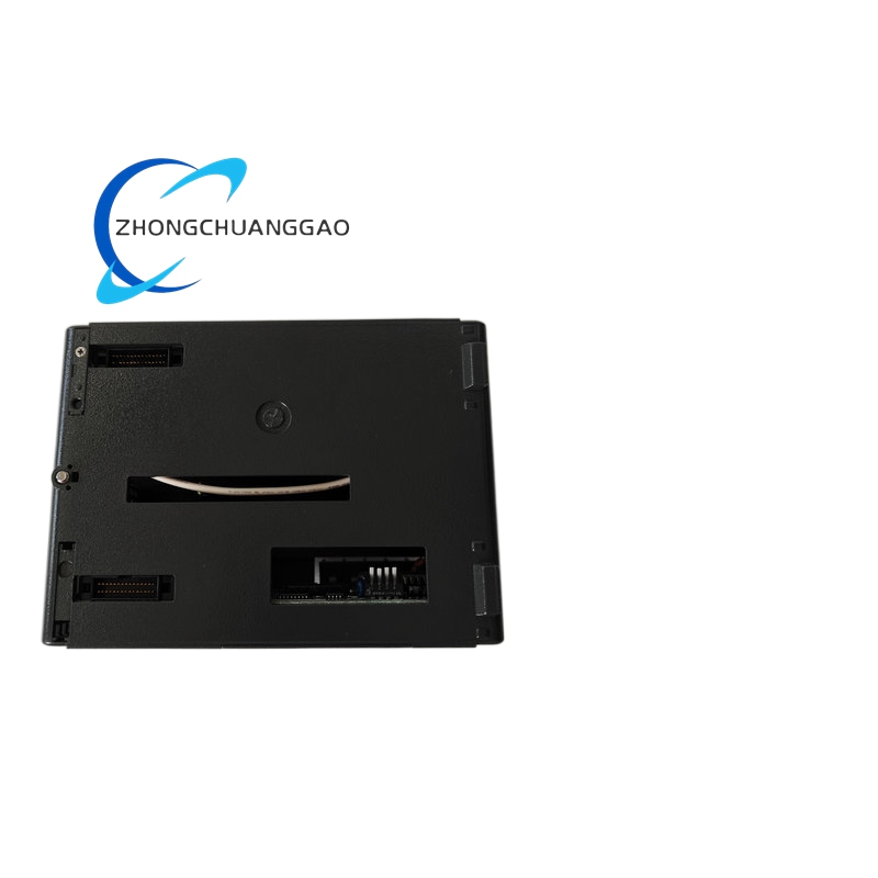
- Rear locking buckle for anti-vibration fixation on DIN rail under mechanical vibration environment
Advantage Highlights
- Compact single-module integration of power supply and communication transceiver, eliminating separate external DC power adapter
- Full galvanic isolation between field bus and PLC mainframe to block ground loop interference
- Wide operating temperature range supporting unheated factory floor and marine engine room deployment
- DIP switch address configuration without software programming for rapid system expansion
- Low weight modular design reduces cabinet space occupation by 40% compared to split remote I/O sets
- Japan-originated industrial-grade component assembly with 100,000-hour MTBF
Applicable Industries
Factory discrete automation assembly lines, marine vessel machinery control, food & beverage packaging equipment, textile processing automation, small-scale material handling conveyor systems
Installation Requirements
- Mount on standard 35 mm DIN rail, vertical installation orientation strictly enforced
- Maintain minimum 20 mm vertical clearance above and below module for heat dissipation airflow
- Shielded twisted pair communication cable grounding single-end only at PLC master cabinet side, field slave end shielding floating
- External 24VDC power circuit must equip 5 A slow-blow fuse for short-circuit protection
- Install EMC ferrite ring on power input cable within 15 cm of module terminal block
Usage Precautions
- Forbid operation under ambient humidity exceeding 95% with water condensation on housing surface
- Do not route communication bus cable parallel to high-current AC power cables within 30 cm distance
- Strictly avoid input voltage exceeding 28 VDC, overvoltage will permanently damage internal isolated power circuit
- Conduct annual insulation resistance test per maintenance schedule to verify circuit isolation performance
- Store in low-dust constant temperature warehouse when not in service, prevent PCB metal terminal oxidation



























Reviews
There are no reviews yet.