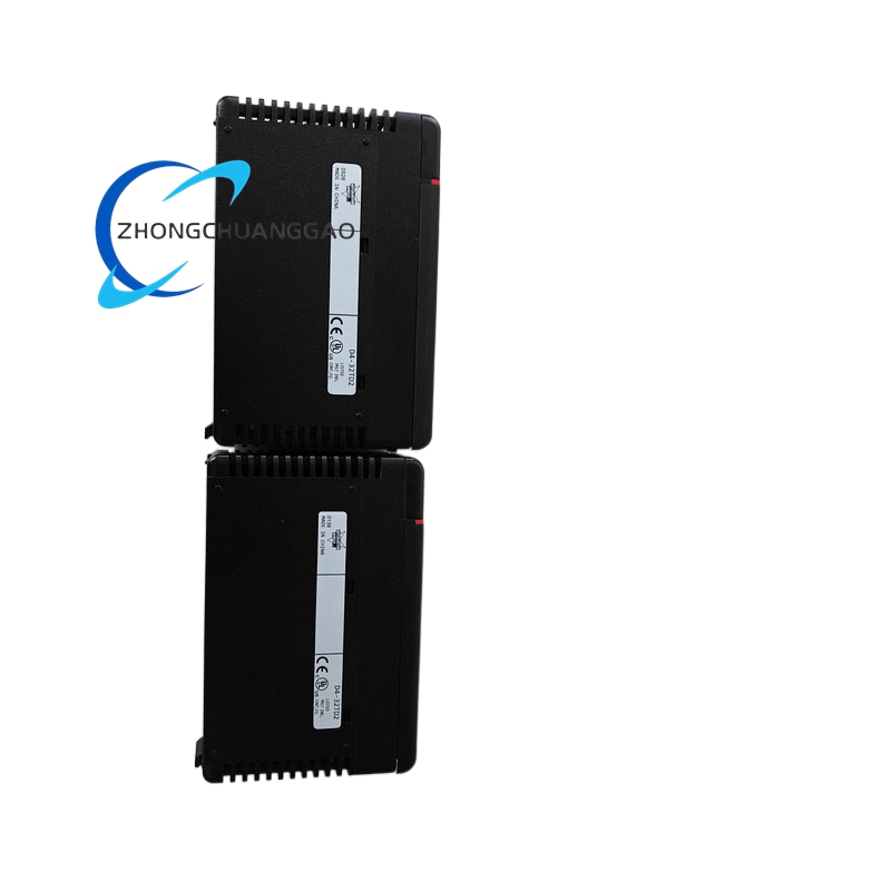
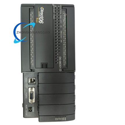
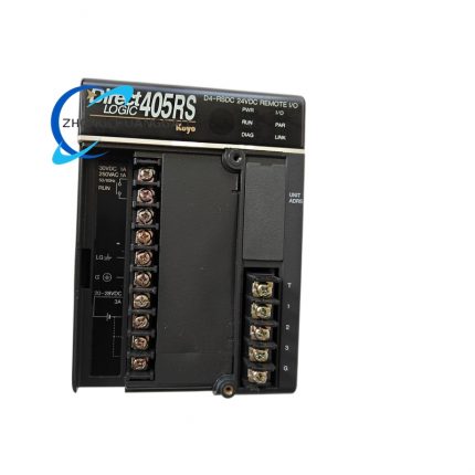
KOYO D4-32TD2

Product Introduction

High-density modular main CPU unit with integrated digital I/O terminals, supporting multi-slot rack I/O expansion modules for medium-scale sequential and motion automation control. Equipped high-speed pulse output channels, multi-protocol serial communication interfaces and expandable program memory, targeted for automated machinery with complex multi-point discrete signal processing requirements.
Category:
Description

Technical Specifications

  • Mounting Standard: Horizontal rack plug-in main unit, compatible with D4 series expansion rack backplane
  • Overall Dimensions (W × H × D): 140 mm × 120 mm × 90 mm
  • Net Unit Weight: 0.65 kg
  • Main Power Supply Input: 24 V DC ±10%
  • Onboard Integrated Digital I/O Layout: 16 DC sink/source compatible digital inputs, 16 DC sinking transistor digital outputs
  • Digital Input Signal Rating: 24 V DC, input current 6 mA per channel
  • Digital Output Single Channel Rated Load: 0.5 A DC per transistor channel, total combined maximum output current 8 A
  • High-Speed Pulse Output Channels: 4 independent 100 kHz differential pulse output ports for stepper/servo axis positioning
  • Internal Base Program Memory: 16 K ladder logic program steps, expandable to 32 K via memory cartridge
  • Data Register Capacity: 1024 16-bit general purpose registers, 256 holding registers for Modbus communication
  • Serial Communication Interfaces: 1 × RS232 programming port, 2 × isolated RS485 ports (Modbus RTU master/slave selectable)
  • Maximum Supported Expansion I/O Modules: 8 D4 series digital/analog expansion modules via rack backplane
  • Minimum Program Scan Cycle Speed: 0.2 ms per 1 K program steps
  • Timer Range: 0.01 s–9999 s high-precision timing function
  • 32-bit High-Speed Counter Maximum Count Frequency: 50 kHz single channel
  • Operating Ambient Temperature: 0 °C to +60 °C
  • Storage Temperature Band: -20 °C to +75 °C
  • Relative Humidity Operating Range: 5%–95% RH, non-condensing atmosphere
  • Galvanic Isolation Rating: 1000 V AC between rack power circuit and field I/O signal circuits
  • Compliance Certifications: CE EMC industrial standard, UL 61131 safety certification

Function Features

  1. High-density 16DI/16DO onboard I/O layout reduces initial expansion module quantity for medium-scale automation equipment
  2. Four independent 100 kHz high-speed differential pulse output channels support multi-axis servo/stepper synchronous positioning without external motion controllers
  3. Dual isolated RS485 serial ports configurable as Modbus RTU master or slave for multi-device network communication
  4. Expandable program memory via removable memory cartridge for large complex ladder logic and production recipe storage
  5. Support for full IEC standard ladder logic instructions, including floating-point arithmetic, PID closed-loop control and interrupt subroutines
  6. Hardware short-circuit independent protection circuit on every digital transistor output channel to isolate single channel fault without full system shutdown
  7. 32-bit high-speed hardware counter function processes high-frequency encoder feedback signals for position measurement tasks
  8. Complete system and channel diagnostic LED indicator array visualizes power, RUN, communication fault, I/O channel on/off operating state

Performance Parameters

  • Full 16 K base program memory single scan cycle maximum duration: 3.2 ms
  • Digital input software filter adjustable delay range: 0.1 ms–200 ms
  • RS485 communication configurable baud rate range: 2400 bps–38400 bps
  • High-speed pulse output positioning resolution: 32-bit target position register
  • Data register power-off retention period: Minimum 30 days via internal lithium backup battery
  • Backplane expansion module data refresh latency: < 0.3 ms per connected expansion module
  • Interrupt subroutine trigger response latency: ≤ 0.1 ms upon hardware interrupt signal input

Material Composition

  • Main unit front panel: Black flame-retardant ABS plastic with printed channel identification and status legend
  • Rack mounting frame: Die-cast aluminum alloy with matte black oxidation anti-corrosion coating
  • Main control circuit board: Multi-layer FR4 high-temperature industrial printed circuit board
  • Backplane edge connector: Gold-plated copper alloy contact pins for long-term expansion module plugging durability
  • I/O terminal blocks: Glass-filled PA66 thermoplastic with tin-plated copper screw terminals
  • Pulse drive and communication components: Industrial differential signal transceivers, high-speed switching transistors
  • Backup power component: Replaceable industrial grade lithium RTC and data retention battery

Structural Characteristics

  • Horizontal plug-in rack main unit design compatible with dedicated D4 series multi-slot expansion backplane rack
  • Front panel layout: Channel group I/O LED indicators, RUN/ERR/COM system status LEDs, RS232 D-Sub programming connector
  • Front side detachable terminal cover protects onboard DI/DO wiring terminals from accidental short-circuit contact
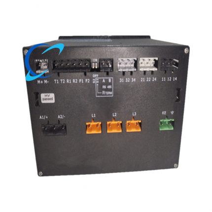
  • Rear panel layout: Rack backplane gold-plated edge connector, dual RS485 communication terminal blocks, 24 V DC power supply terminals
  • Internal segmented PCB layout: Main CPU control zone, high-speed pulse motion drive zone, I/O signal isolation zone, backplane communication interface zone
  • Integrated passive aluminum heat sink bonded to pulse output drive circuit area for heat dissipation
  • IP20 overall protection rating for cabinet internal installation only
  • Dual side plastic lock levers for secure rack mounting and easy unit extraction during maintenance

Working Principle

  1. Regulated 24 V DC rack power supply passes through multi-stage EMI filtering and surge protection circuits to supply CPU, I/O drive, communication and pulse generation hardware
  2. 16-channel isolated digital input conditioning circuits convert external 24 V DC sensor discrete signals into digital logic levels stored in CPU input image registers
  3. Main CPU executes ladder logic main program and interrupt subroutines within fixed deterministic scan cycle, processing timing, counting, arithmetic and PID control instructions sequentially
  4. Calculated output logic values are transmitted to onboard 16-channel sinking transistor drive circuits to switch external DC actuator loads; four dedicated high-speed pulse generators output differential positioning pulses to servo/stepper drive units
  5. Rear backplane bus interface chip establishes high-speed bidirectional data exchange with connected D4 series analog/digital expansion modules, extending total system I/O signal capacity
  6. Dual isolated RS485 transceivers exchange Modbus RTU register data with upper HMI, remote slave PLC or field sensor network devices; RS232 port connects PC programming software for program upload/download and online monitoring
  7. Internal lithium backup battery maintains data register values, counter accumulated data and system clock timestamps during extended power outage events
  8. Independent per-channel short-circuit detection hardware monitors transistor output load current; cuts single channel drive signal and lights channel fault LED upon overcurrent detection without interrupting other I/O channel operation

Advantage Highlights

  1. High-density 32-point onboard I/O reduces initial hardware procurement cost and rack space occupation for medium-scale automation equipment
  2. Four-channel independent 100 kHz differential pulse output eliminates external motion control module expense for multi-axis positioning machinery
  3. Dual configurable Modbus RS485 ports support simultaneous master network control and slave upper system data upload
  4. Expandable memory cartridge supports storage of complex multi-product production recipes without external data storage hardware
  5. Per-channel independent output short-circuit protection limits fault impact to single load channel only, ensuring continuous operation of remaining machine logic
  6. 30-day power-off data retention avoids production parameter loss during long-term facility power shutdown events
  7. Modular expandable rack architecture allows flexible addition of analog I/O, thermocouple and relay output expansion modules as production process requirements expand

Applicable Industries

High-speed automated packaging production lines, injection molding machine auxiliary control systems, metal CNC machining peripheral automation, multi-axis textile weaving machinery, electronic component assembly equipment, warehouse multi-station conveyor control panels, food processing batch automation equipment

Installation Requirements

  1. Horizontally insert main unit into the first slot of standard D4 series expansion rack backplane, fully lock dual side extraction levers to secure rear edge connector mating
  2. Maintain minimum 35 mm vertical air gap between main unit and adjacent rack expansion modules for passive heat sink air circulation
  3. Cabinet internal cooling air flow rate minimum 0.4 m/s to keep pulse drive circuit temperature within rated operating range
  4. Separate high-current actuator load wiring, pulse positioning shielded cables and low-current sensor signal wiring into isolated cable trays with minimum 12 cm separation distance
  5. Connect rack aluminum frame protective earth lug to cabinet main protective earth busbar with 2.5 mm² copper conductor
  6. All RS485 Modbus communication bus wiring must install 120 Ω termination resistors at the two physical endpoints of the entire bus network
  7. Differential pulse output cables for servo/stepper drives must use shielded twisted pair differential cable with single-point shielding grounding at PLC rack cabinet side

Usage Notes

  1. Calibrate high-speed pulse output acceleration and deceleration parameters matching connected servo/stepper motor specifications before initial equipment trial run
  2. Do not operate single transistor output channel with load current exceeding 0.5 A DC to avoid irreversible drive transistor thermal damage
  3. Complete full ladder program and production recipe backup to external PC storage before replacing memory cartridge or upgrading firmware
  4. Replace internal lithium backup battery every 5 years to eliminate data register loss during facility power outages
  5. Avoid routing high-frequency pulse output cables parallel to variable frequency drive power cables without metal shielding conduit separation
  6. Quarterly inspect rack backplane gold-plated edge connectors for oxidation and dust accumulation to prevent expansion module communication failure
  7. Set digital input filter delay value matching mechanical sensor switch bounce time to eliminate false trigger input signals during continuous production operation
Reviews (0)

Reviews

There are no reviews yet.

Be the first to review “KOYO D4-32TD2”

Your email address will not be published. Required fields are marked *

Shipping and Delivery

MAECENAS IACULIS

Vestibulum curae torquent diam diam commodo parturient penatibus nunc dui adipiscing convallis bulum parturient suspendisse parturient a.Parturient in parturient scelerisque nibh lectus quam a natoque adipiscing a vestibulum hendrerit et pharetra fames nunc natoque dui.

ADIPISCING CONVALLIS BULUM

  • Vestibulum penatibus nunc dui adipiscing convallis bulum parturient suspendisse.
  • Abitur parturient praesent lectus quam a natoque adipiscing a vestibulum hendre.
  • Diam parturient dictumst parturient scelerisque nibh lectus.

Scelerisque adipiscing bibendum sem vestibulum et in a a a purus lectus faucibus lobortis tincidunt purus lectus nisl class eros.Condimentum a et ullamcorper dictumst mus et tristique elementum nam inceptos hac parturient scelerisque vestibulum amet elit ut volutpat.