
Emerson 1410S2AA32AD4N7RD
Model Series: 1410 Series — Temperature Transmitter
Product Introduction:
The Emerson 1410S2AA32AD4N7RD is a head-mountable temperature transmitter that accepts RTD (Pt100) input and provides a 4–20 mA HART output. It is designed for direct sensor head mounting in pipe, vessel, or duct applications where space is limited. The transmitter features HART 7 communication for remote configuration and diagnostics.
A-B 1336-BDB-SP31D
Model Series: PowerFlex 525 Series
Product Introduction:
The Allen-Bradley 1336-BDB-SP31D is a 15 HP (11 kW), 480 VAC, 3-phase adjustable frequency drive (VFD) designed for general-purpose motor control in industrial applications. It features an integrated DC bus choke and EMC filter, sensorless vector control, and built-in Ethernet/IP communication for seamless integration into Connected Enterprise architectures.
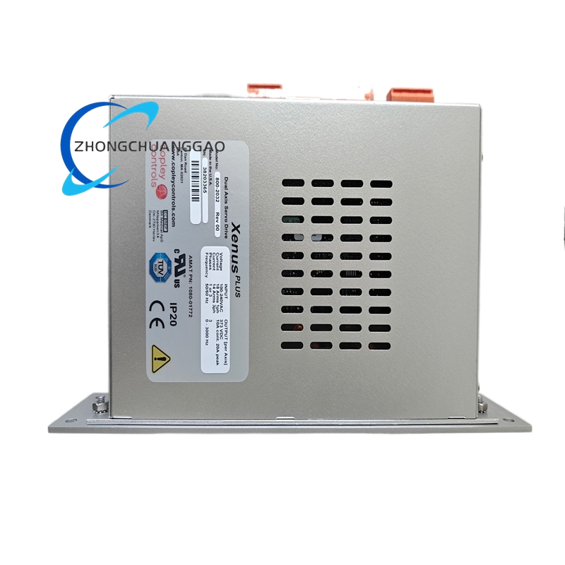
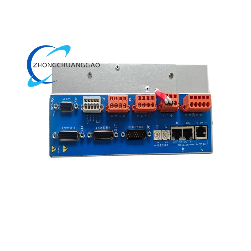
AMAT 1080-01772
Model Series: 1080 Series — Etch Chamber Gas Distribution Components
Product Introduction:
The AMAT 1080-01772 is a precision-engineered gas distribution plate (showerhead) used in Applied Materials dielectric and polysilicon etch chambers. It distributes process gases uniformly across the wafer surface while withstanding high-temperature plasma exposure. The component is part of the upper electrode assembly in AMAT etch platforms.
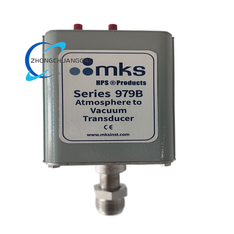
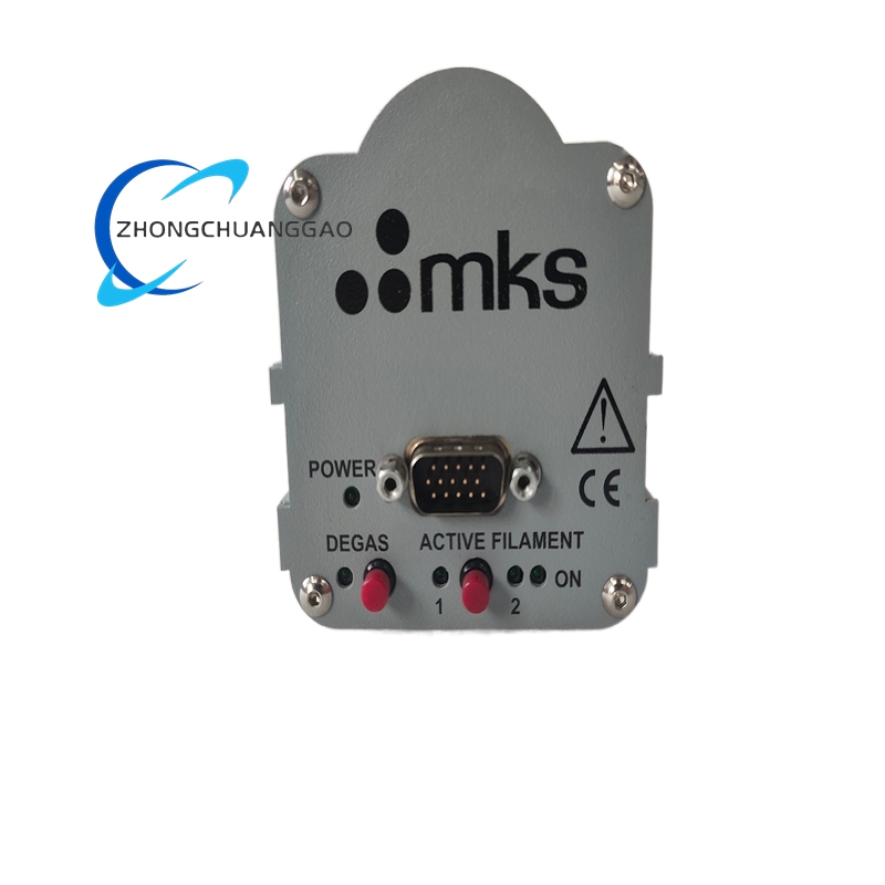
MKS 979B-01-0013
Model Series: 979B Series — Baratron Capacitance Diaphragm Gauge
Product Introduction:
The MKS 979B-01-0013 is a high-accuracy absolute pressure transducer based on the Baratron capacitance manometer principle. It provides precise absolute pressure measurement from atmosphere down to 0.001 Torr, making it ideal for semiconductor process control, vacuum system monitoring, and leak detection applications.
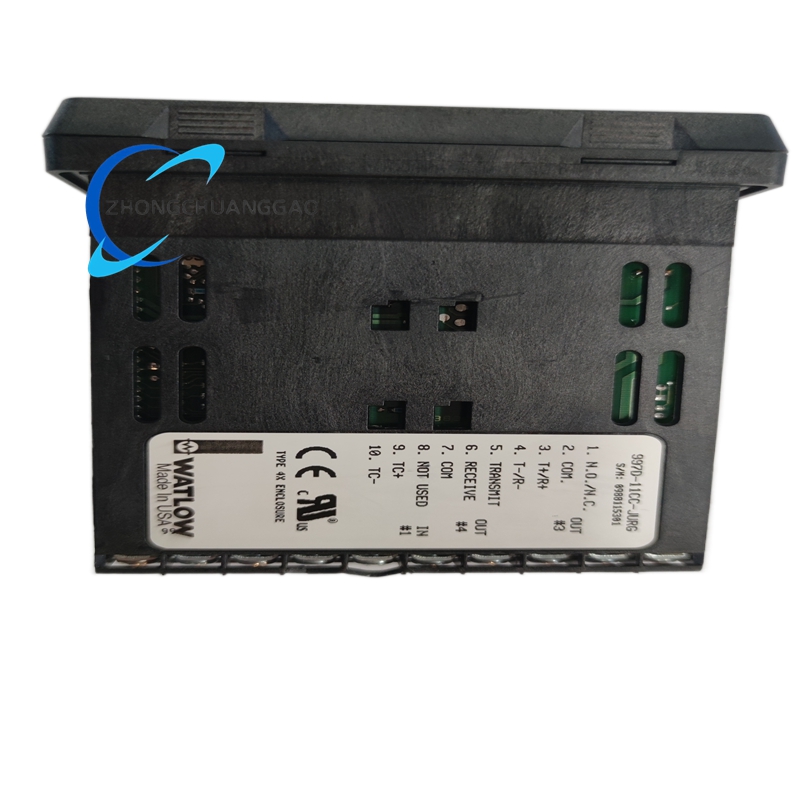
Watlow 997D-11CC-JURG
Model Series: EZ-ZONE PM 997D Series
Product Introduction:
The Watlow 997D-11CC-JURG is a DIN-rail-mountable PID temperature controller with dual relay outputs and universal input capability. It is designed for industrial oven, furnace, and process heating applications requiring precise temperature control with alarms and event logging.
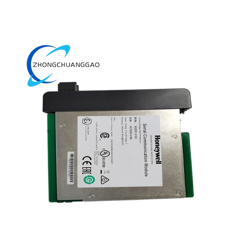
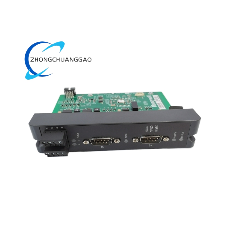
Honeywell 900ES1-0100
Model Series: 900ES Series — General Purpose Pressure Transmitter
Product Introduction:
The Honeywell 900ES1-0100 is a robust, analog pressure transmitter designed for general-purpose gauge pressure measurement in HVAC, process control, and building automation systems. It provides a 4–20 mA current output proportional to the measured pressure with a 316L stainless steel wetted diaphragm.
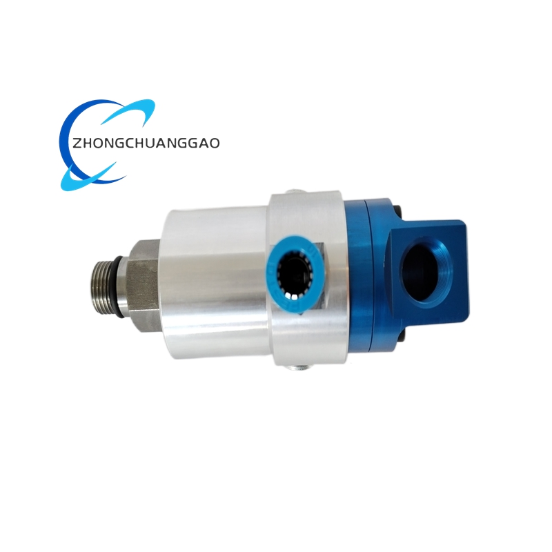
Deublin 904-120-188
Model Series: 904 Series — Multi-Passage Rotary Unions
Product Introduction:
The Deublin 904-120-188 is a multi-passage rotary union designed to transfer multiple fluid or gas media simultaneously between a stationary supply line and a rotating component. It features a modular seal cartridge design with balanced mechanical seals for high-speed rotation in industrial processing equipment.
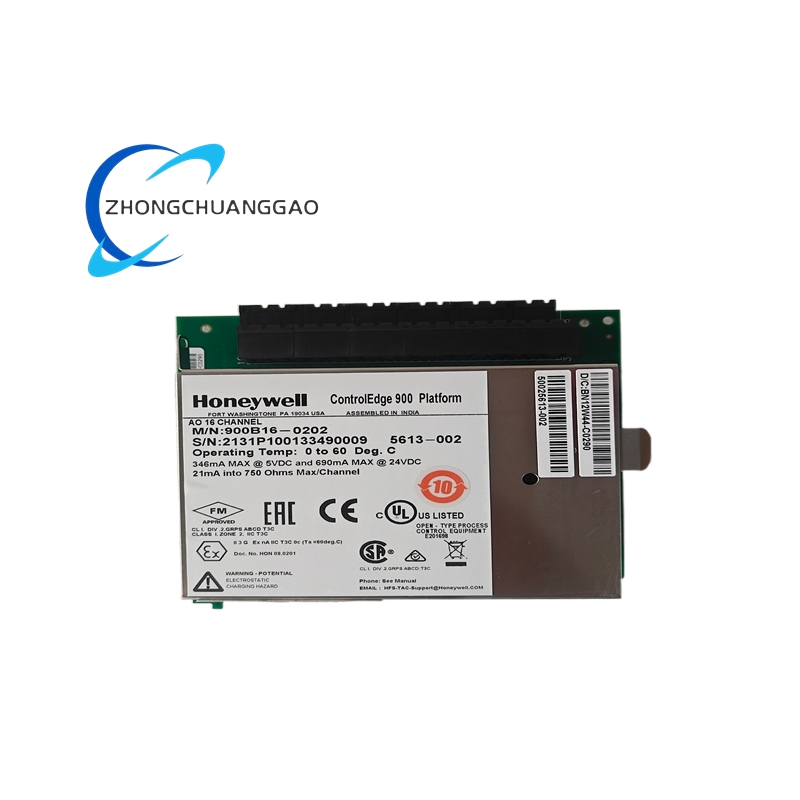
Honeywell 900B16-0202
Model Series: 900B Series — General Purpose Limit Switch
Product Introduction:
The Honeywell 900B16-0202 is a heavy-duty snap-action limit switch designed for industrial machine control, safety interlocking, and position sensing. It provides reliable ON/OFF switching with a lever actuator for precise mechanical actuation in harsh environments.
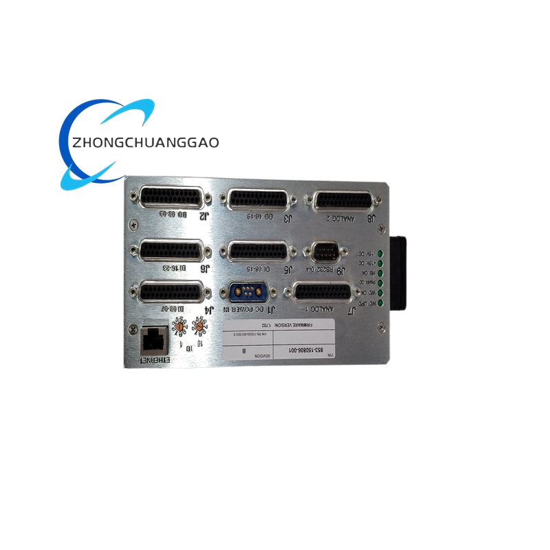
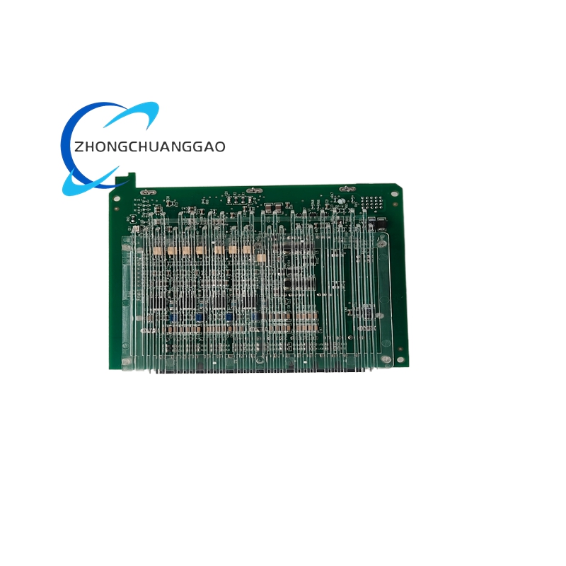
LAM 853-150806-001
Model Series: 853 Series — 853 Etch System Component Family
Product Introduction:
This part is a precision-machined sub-assembly used within Lam Research 853 series plasma etch chambers. It functions as an internal RF-powered electrode or gas distribution showerhead assembly that directly interfaces with the plasma generation zone. The component ensures uniform gas dispersion and controlled ion bombardment across the wafer surface during dielectric or polysilicon etch processes.
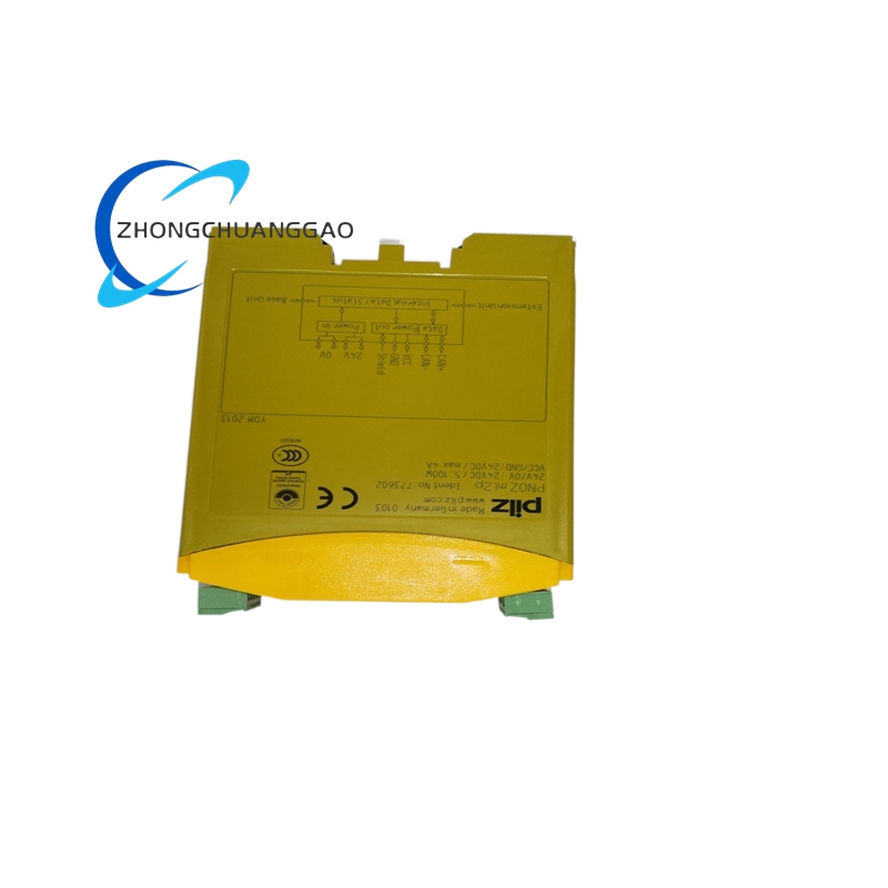
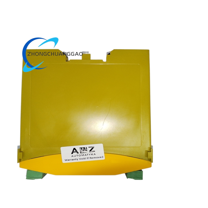
PILZ 773602
Product Name: Pilz PNOZ X1 24VAC 24VDC Safety Relay, Part Number 773602
Product Overview: This is a Pilz PNOZ X1 compact safety relay. It is the entry-level model in the PNOZ X family, designed for simple safety functions such as emergency stop monitoring, safety door switching, and two-hand control in smaller machines.
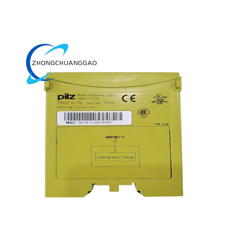
PILZ 773731
Product Name: Pilz PNOZ X2.8P Safety Relay, Part Number 773731
Product Overview: This is a Pilz PNOZ X2.8P programmable safety relay. Pilz is a global leader in safety automation technology. The PNOZ X2 series provides compact, programmable safety functions for machine guarding, emergency stop, and safety door monitoring applications.
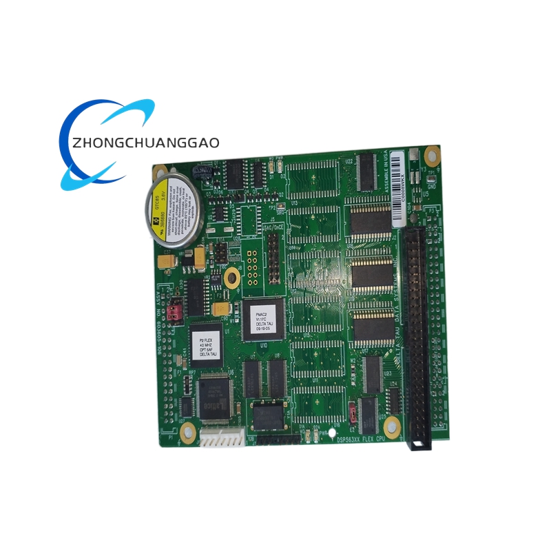
DATA 603605-106
Product Name: Data I/O Serial Communication Module, Part Number 603605-106
Product Overview: This is a Data I/O (Data Input/Output) brand serial communication interface module. Data I/O is a global manufacturer of device programming, industrial automation, and IoT connectivity solutions. This module provides RS-232/RS-485 serial communication for integration with PLCs, SCADA systems, and data loggers.
")
")


Reviews
There are no reviews yet.