Technical Specifications:
- Fieldbus Standard: Foundation Fieldbus H1 (IEC 61158-2)
- Communication Speed: 31.25 kbps
- Number of Segments: 2 independent H1 segments (32 devices per segment, 64 total)
- Supported Device Types:
- AI (Analog Input) — FF transmitters
- AO (Analog Output) — FF valve positioners
- PID (Control Block) — FF controllers
- DI (Digital Input) — FF switches
- DO (Digital Output) — FF actuators
- Power Supply to Bus: 9–32 VDC (module provides bus power to field devices)
- Bus Current Capacity: 120 mA per segment (sufficient for up to 32 devices)
- Intrinsic Safety (IS): available in IS barrier version — IEC 60079-11 compliant
- Uo = 9.0V DC, Io = 90 mA, Po = 0.405W, Co = 0.047μF, Lo = 0mH (IS version)
- Non-IS Version: Uo = 32V DC, Io = 120 mA, Po = 1.92W
- Isolation: 1,500 VDC between bus and backplane
- Operating Temperature: 0°C to 60°C (32°F to 140°F)
- Protocol Stack: FF H1 — Physical Layer, Data Link Layer, and Application Layer (LLC)
Functional Features:
- Dual independent H1 segments — allows separation of safety-critical and non-critical devices
- Built-in function block execution — supports PID, arithmetic, and logic function blocks directly on the module (offloads processor)
- Device description (DD) management — automatically loads DD files from I/A Series engineering database
- Scheduled and unscheduled communication — supports both cyclic and acyclic data exchange
- Device diagnostics: Per-device status, communication error count, quality flag
- Hot connection/disconnection — devices can be added or removed without system shutdown (if segment power permits)
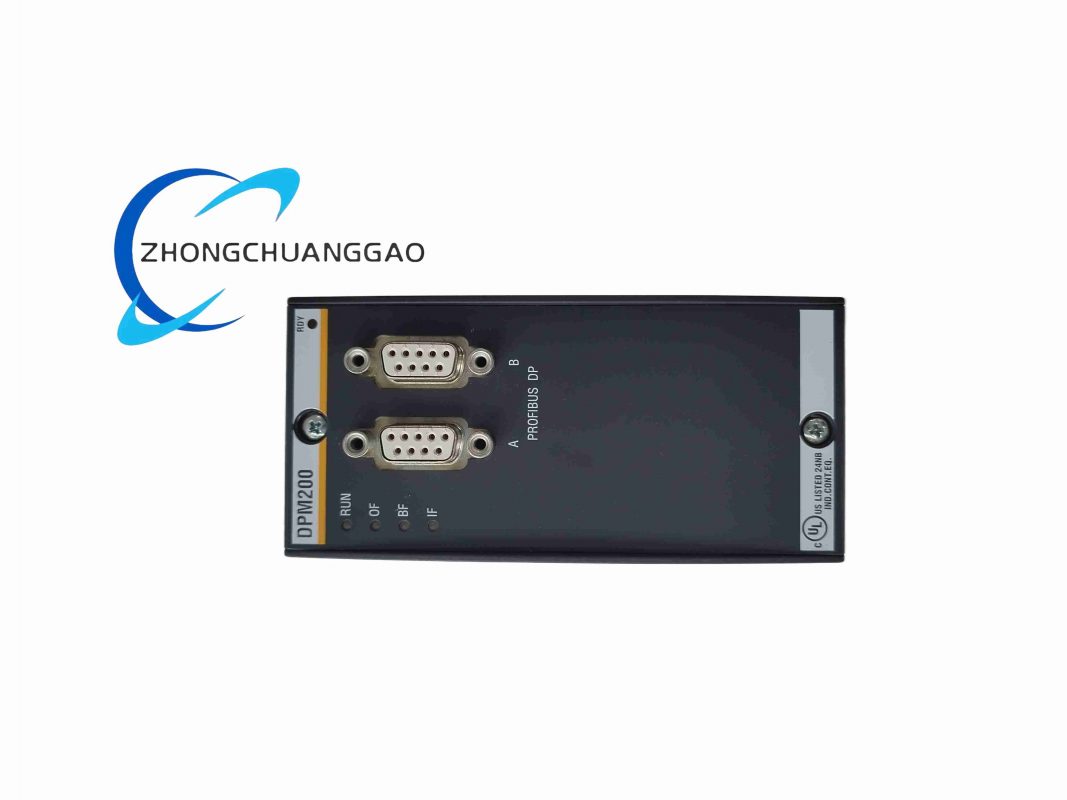
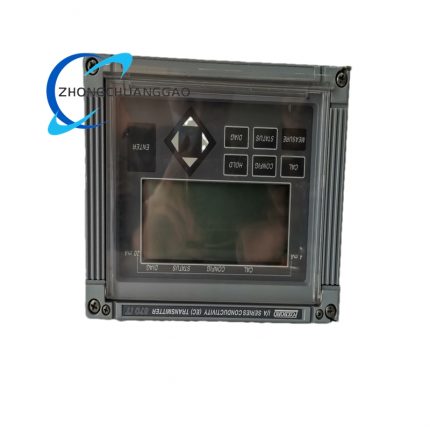
- Front Panel LEDs: Segment 1 OK, Segment 2 OK, Bus Power, and Fault indicators
Performance Parameters:
- Cyclic Data Update Rate: 100 ms to 1 second (configurable per device)
- Acyclic Data Rate: Up to 10 transactions per second per segment
- Maximum Cable Length per Segment: 1,900 meters (6,234 feet) (with appropriate cable and terminators)
- Number of Devices per Segment: 32 maximum (including branches)
- Maximum Branches per Segment: 4 branches (with repeaters)
- Device Addressing: 0–31 per segment (set via DIP switches or software)
Material Composition:
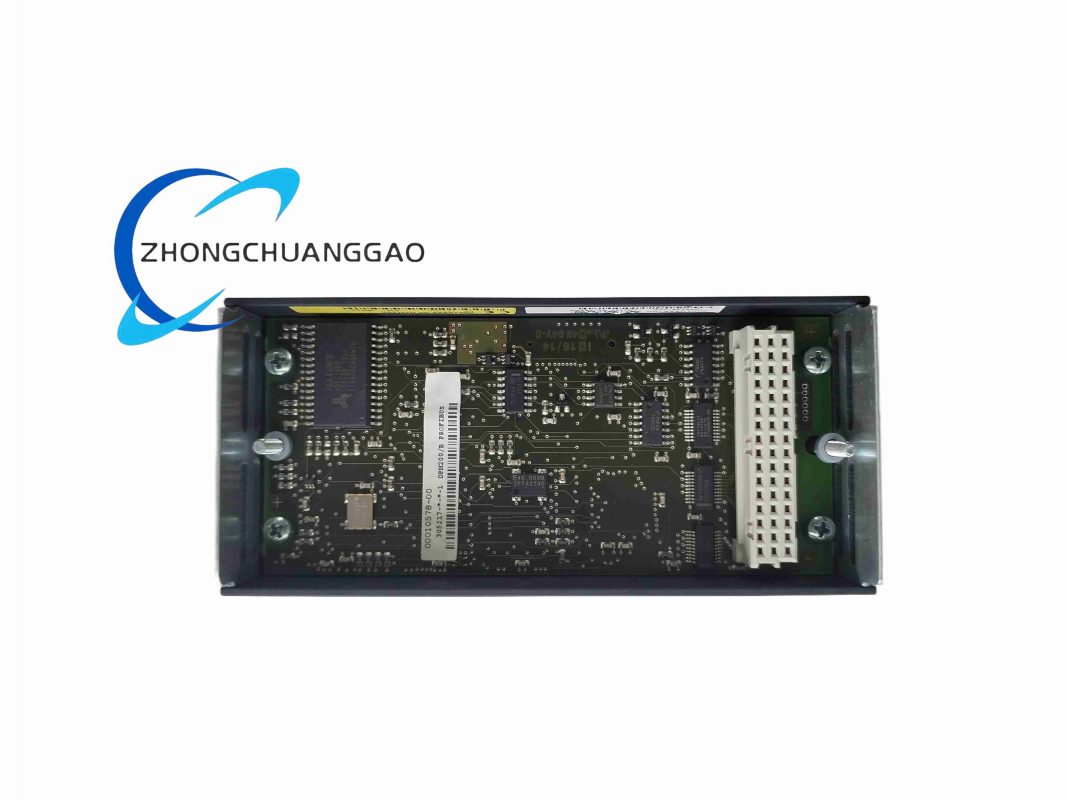
- PCB: 4-layer FR-4 with Fieldbus Physical Layer (PHY) IC
- IS Barrier (IS version): Zener diode-based barriers with galvanic isolation — IEC 60079-11 certified
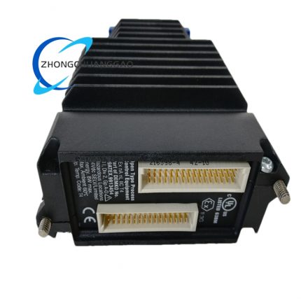
- Fieldbus Connector: Screw-terminal block with integrated bus terminator switches (120Ω)
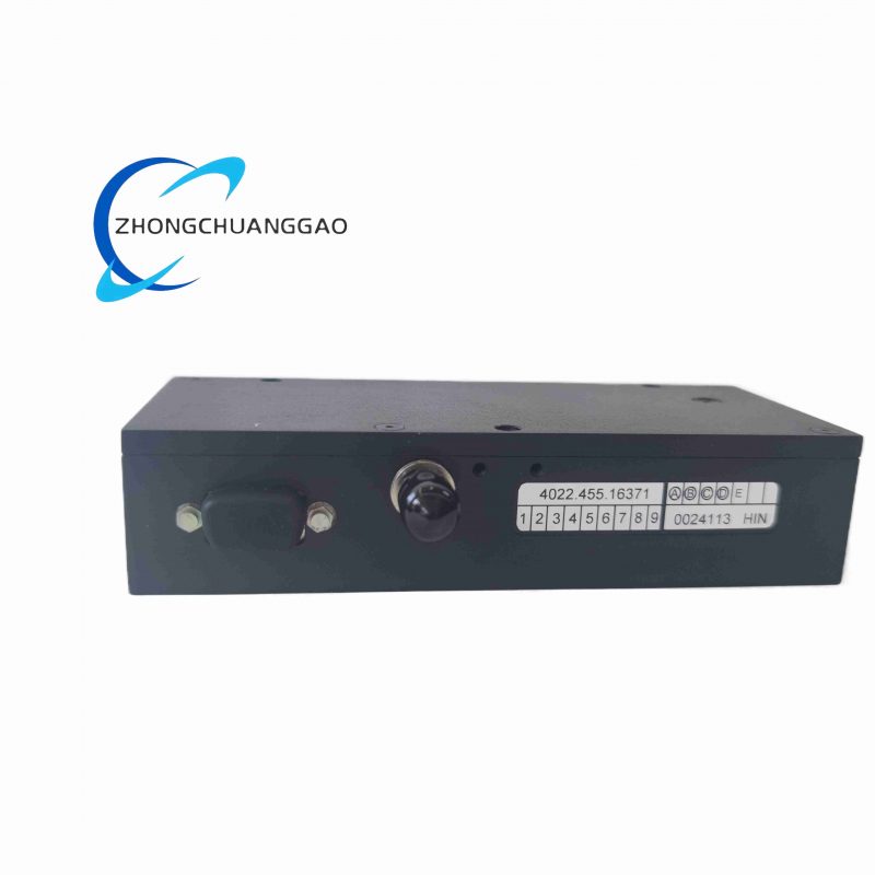
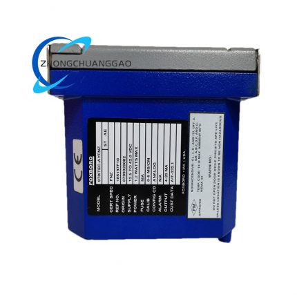
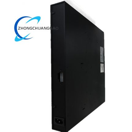
- Enclosure: Steel with zinc-nickel plating; IS version has blue painted identification band
- Connectors: Dual backplane connectors; screw-terminal field wiring connectors
Structural Characteristics:
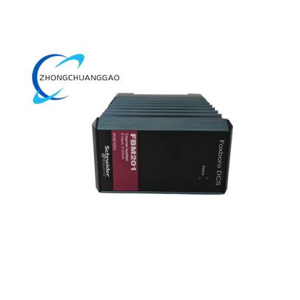
- Form Factor: Standard Eurocard module (160 mm × 233 mm)
- Mounting: Horizontal rack mount in I/A Series chassis
- Field Wiring: Screw-terminal connectors — bus trunk and spur connections
- Weight: Approximately 0.8 kg (1.76 lbs)
Working Principle:
The FEM100 contains the complete FF H1 Physical Layer and Data Link Layer stack. It generates the 31.25 kbps Manchester-encoded signal on the H1 bus and receives signals from FF devices. Each device on the bus has a unique address (0–31). The module polls each device cyclically (every 100 ms to 1 second, configurable) to read process variables (PV) and write setpoints (SP) and output values (OUT). Acyclic reads/writes are handled on demand by the processor. The module buffers all FF data and transfers it to the FBM219 processor via the backplane during each scan cycle. The processor reads the buffered PV, SP, and OUT values and executes control logic. For the IS version, the barrier circuitry limits energy to the bus to below intrinsic safety ignition thresholds, allowing installation in hazardous areas (Zone 0, 1, or 2).
Advantages & Highlights:
- Dual H1 segments — maximum flexibility in device arrangement
- 32 devices per segment — supports large field installations on one module
- Built-in FF function blocks — PID control can execute on the module, reducing processor load
- Intrinsic safety option — direct connection to hazardous area devices without external barriers
- Hot-swap capable — add/remove devices without system shutdown
Applicable Industries:
- Oil and Gas (hazardous area field instrumentation — FF pressure transmitters, FF control valves)
- Chemical (FF flow meters, FF analyzers, FF positioners)
- Power Generation (FF turbine control, FF boiler instrumentation)
- Pharmaceutical (FF batch control, FF analytical instruments)
- Mining (FF instrumentation in hazardous locations)
Installation Requirements:
- Install in any available chassis slot — recommend slot adjacent to FBM219 for optimal performance
- Terminate each H1 segment with 120Ω resistor at both ends — use module-integrated terminator switches
- Use Fieldbus-approved cable — Type A, Shielded Twisted Pair, 100Ω characteristic impedance
- Maximum segment length: 1,900 meters including all branches and spurs
- IS version: follow IEC 60079-14 wiring rules — blue cable sheath, dedicated IS grounding
Usage Precautions:
- Always terminate both ends of each H1 segment — unterminated segments cause communication failure
- Maximum 32 devices per segment — exceeding this requires additional FEM100 module or repeater
- IS version: do not connect non-IS devices to IS segment — defeats intrinsic safety protection
- Verify device addresses are unique within each segment — duplicate addresses cause bus collision
- Do not exceed 120 mA bus current per segment — use bus-powered devices only within current budget
- Cable type must be FF-approved Type A — using non-approved cable causes signal degradation and communication errors


")
")


Reviews
There are no reviews yet.