- Standard Industry Alias: Two-Channel Closed-Loop LVDT/RVDT Feedback Actuator Drive Module under NetCon Control Platform
- Platform Affiliation: MicroNet Distributed Control System & NetCon modular control system standard accessory module
2. Product Brief Introduction
- This unit is a dedicated rack-mounted digital closed-loop actuator drive module belonging to Woodward NetCon/MicroNet modular control product platform, independently developed to implement dual-channel independent servo drive and position closed-loop regulation for electro-hydraulic and electromagnetic prime mover actuators.
- The module receives digital position setpoint commands from upper-level MicroNet CPU master module via dedicated internal backplane bus, collects real-time position feedback signals from LVDT or RVDT position sensors mounted on each controlled actuator, calculates deviation value and outputs regulated driving current to adjust actuator mechanical stroke position.
- Each built-in control channel supports installation of maximum two sets of position feedback sensors for redundant position detection, integrates full-range circuit fault diagnosis logic and hardware interlock protection circuit, automatically cuts off channel driving output once abnormal circuit status is detected.
- It supports offline parameter configuration and real-time operational data uploading via RS232/RS485 serial communication port with official Woodward ToolKit & GAP Editor configuration software, widely matched with gas turbine, steam turbine, internal combustion engine governing fuel actuator and industrial pipeline valve actuator control systems.
3. Complete Technical Specifications
3.1 Power Supply Specifications
- Main Logic Operating Power Input: +5 VDC @ 0.5 A fixed rated input parameter
- Actuator Driving Power Input: +24 VDC (±10% tolerance, valid continuous input range 21.6VDC~26.4VDC), rated operating input current 1 A
- Total full-load rated power consumption of complete module: 26.5 W
- Isolated auxiliary excitation power supply for feedback transducer: 7 VAC sinusoidal excitation output dedicated for LVDT/RVDT sensor power supply
3.2 Channel Drive Electrical Parameters
- Single channel continuous rated actuator driving output current: 200 mA DC; instantaneous peak allowable output upper limit: 245 mA DC
- Max permissible load resistance formula for each output channel: Fixed value = 10 ÷ Actual Channel Operating Current (Unit: Ampere)
- Full-scale output current tolerance: ±1% of full rated output range
- Feedback signal readback current tolerance: ±5% of full-scale measuring range
3.3 Feedback Input Specification
- Supported feedback sensor types: LVDT linear variable differential transformer, RVDT rotary variable differential transformer exclusively
- Maximum feedback device configuration per independent channel: Two separate feedback transducers for redundant position collection
- Input impedance of feedback signal acquisition circuit: 2.2 MΩ per single signal terminal
3.4 Communication Interface Spec
- Standard onboard communication ports: RS-232, RS-485 dual serial interface as factory default; CAN bus communication available via optional onboard expansion chip configuration
- Dedicated internal backplane bus: MicroNet proprietary parallel rack bus for data interaction with system master CPU module; only compatible with official MicroNet gray low-density discrete rack cable, black digital bus cable is prohibited for wiring access
3.5 Ambient Environmental Spec
- Continuous long-term operating ambient temperature range: -40 ℃ ~ +70 ℃
- Non-operational sealed storage temperature range: -55 ℃ ~ +85 ℃
- Working ambient humidity scope: 5%~95% relative humidity under non-condensing working condition
- Allowable working altitude without parameter derating: ≤2000 meters above sea level
- Protection grade for module housing: Front panel IP20, internal PCB coated with three-proof conformal coating against damp and corrosive gas erosion
3.6 Physical Dimension & Weight Spec
- Overall outer dimension: 260.35 mm (Width) × 247.65 mm (Height) × 25.4 mm (Depth) / 10.25 in ×9.75 in ×1.0 in
- Single unit net weight without accessory wiring: 0.93 kg
- Standard rack mounting slot size: Compliant with MicroNet system 1U modular rack standard dimension
4. Core Function Features
- Dual independent isolated control channel design: Two fully separated closed-loop actuator drive channels operate without mutual electrical interference, supporting independent forward-acting and reverse-acting output characteristic configuration per single channel.
- Dual redundant feedback acquisition function: Each channel receives two sets of position feedback signals simultaneously, module internal logic automatically switches to spare feedback channel once primary feedback circuit fails to ensure continuous closed-loop control.
- Full-range multi-dimensional fault diagnosis function: Real-time monitoring for transducer excitation circuit abnormality, feedback signal loss, driver overcurrent, logic power undervoltage, backplane communication interruption and internal CPU operation exception; corresponding fault status locked and indicated via front panel LED indicator.
- Hardware safety interlock output logic: All channel driving outputs cut off immediately when communication connection between module and master CPU is lost to avoid uncontrolled actuator misoperation.
- Multi-mode output characteristic setting: Supports forward fuel increasing output and reverse fuel increasing output two working modes configurable via parameter software, matching single actuator and tandem dual actuator installation application scenarios respectively.
- Password-protected parameter storage mechanism: All user configuration parameters permanently stored in onboard nonvolatile memory with multi-level access password encryption to prevent unauthorized parameter modification.
- Real-time data uploading function: Cyclically upload channel setpoint value, actual feedback position value, operating current and fault code data to upper master controller via backplane bus and serial communication interface for remote system monitoring.
5. Detailed Performance Parameters
- Nominal closed-loop position control accuracy under 25℃ standard ambient condition: 0.25% of full stroke range (excludes original transducer measurement error)
- Closed-loop control response delay from feedback deviation detection to driving output adjustment: ≤10 ms full system reaction time
- Internal master control core operating frequency: Fixed 32MHz industrial-grade RISC microprocessor core clock frequency
- Onboard nonvolatile storage capacity: 32KB EEPROM for permanent preservation of all user configuration parameters without external backup power supply
- Feedback signal circuit harmonic suppression ratio against 2nd~30th order AC interference: ≥45dB fixed filter parameter
- Minimum configurable single-channel actuator stroke resolution: 0.01% of full rated mechanical travel range
6. Material Composition Details
6.1 Outer Enclosure Material
- Module outer rack frame: Aviation-grade extruded aluminum alloy with black oxidation anti-corrosion surface treatment, high mechanical shock resistance
- Front panel cover plate: Cold rolled steel sheet with matte black electrostatic spraying anti-rust coating
- Terminal dustproof baffle: Modified PA66 flame retardant insulating nylon (UL94-V0 fire protection rating)
6.2 Internal Core Component Raw Materials
- Main control PCB substrate: FR-4 full copper-clad glass fiber epoxy board, whole board covered with transparent polyurethane conformal three-proof coating for moistureproof, mildewproof and anti-corrosion protection
- Core control chip: Wide-temperature industrial grade CMOS 32-bit RISC microcontroller chip rated for -40℃~+85℃ continuous stable operation
- Feedback excitation circuit component: High-precision ferrite core isolation transformer, high-temperature solid aluminum electrolytic capacitor, silicon epitaxial rectifier diode
- External wiring connector: Tin-plated phosphor copper conductive terminal with PA66 insulating plastic base
- Indicator LED part: Industrial high-brightness long-life semiconductor light-emitting diode
7. Structural Feature Description
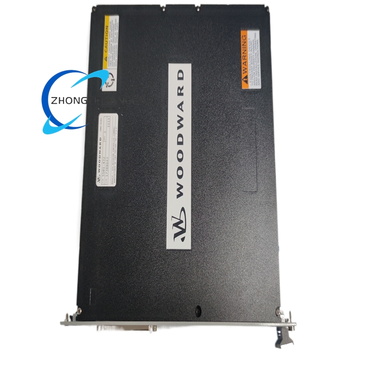
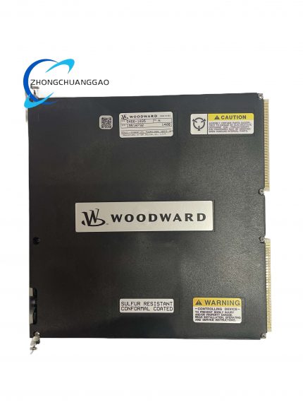
- Overall standard MicroNet rack pluggable modular structure, whole unit designed for direct insertion into system master rack card slot with spring-type locking buckle on both side edges for fixed installation without additional fixing screws.
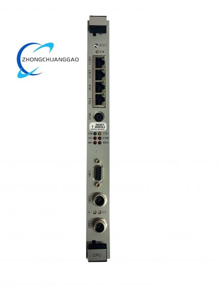
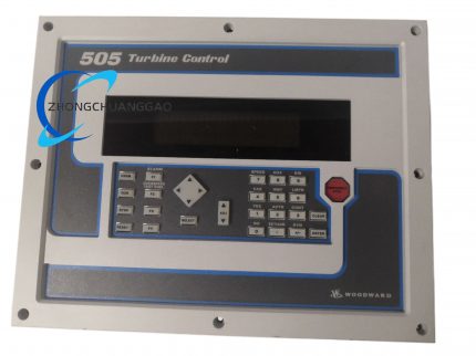
- Front panel zoning layout: Upper area equipped with red fault status LED indicator lamp, middle area printed with Woodward brand marking and part number identification, lower section reserved serial communication interface and configuration port position; red status LED keeps steady lighting for permanent communication failure and flashes for partial channel fault state.
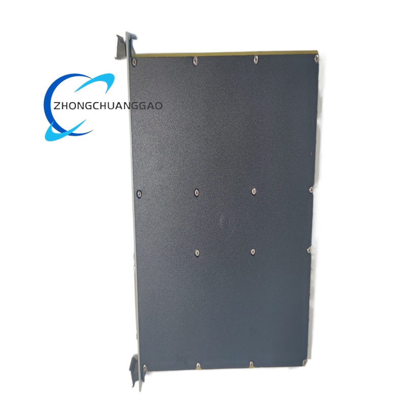
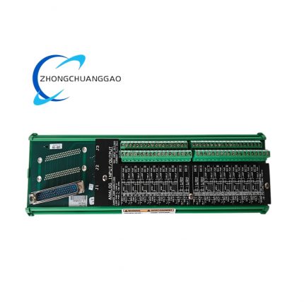
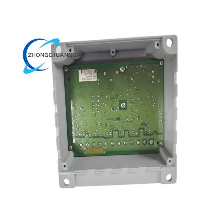
- Rear end layout: Dedicated gold-plated multi-core backplane bus connector for rack internal data and power connection, side independent external terminal socket for actuator driving wiring and feedback sensor wiring separation layout to isolate strong current and weak signal circuit space.
- Internal layered cavity partition: Power supply layer circuit, feedback signal acquisition layer circuit and microprocessor control layer circuit fixed on independent plastic insulation support columns with separating baffles to eliminate electromagnetic cross-interference between different functional circuits.
- Pre-reserved onboard expansion chip slot for optional CAN communication module welding, realizing flexible communication function upgrade without changing main hardware structure.
8. Working Principle
- Command Receiving Stage: The module obtains real-time actuator target position setpoint digital command from upper MicroNet master CPU through rack backplane bus and temporarily stores target value into internal register.
- Feedback Signal Sampling Stage: Onboard dedicated excitation circuit outputs fixed 7VAC excitation power to connected LVDT/RVDT transducers; feedback sensors convert mechanical actuator stroke displacement into proportional AC analog signal, then module built-in isolation sampling circuit finishes signal filtering, rectification and A/D digital conversion before transmitting processed position data to core microprocessor.
- Deviation Calculation Stage: Internal MCU calculates numerical difference between preset target position value and real-time collected actual feedback position value via closed-loop control algorithm, compares calculated deviation with user preset dead zone threshold parameter stored in EEPROM.
- Driving Output Regulation Stage: When position deviation exceeds set dead zone value, control logic adjusts the magnitude and direction of channel output driving current proportionally; changed driving current acts on controlled electromagnetic/hydraulic actuator to drive mechanical part moving toward target stroke position and gradually reduce position error until deviation falls within allowable dead zone range.
- Fault Interlock Execution Stage: Any abnormal state including feedback open circuit, driver overcurrent and communication interruption triggers internal hardware interlock circuit to cut off corresponding channel output immediately, meanwhile front panel fault LED activates and fault code is stored inside memory for subsequent maintenance inquiry.
9. Product Advantage Highlights
- Dual redundant feedback design improves system operational safety, single set of feedback sensor failure cannot lead to complete channel control loss, greatly reducing unit emergency shutdown risk for turbine and genset critical governing system.
- Ultra-wide operating temperature range and full conformal-coated PCB structure realize stable continuous running under high-humidity, dusty and temperature-fluctuating harsh industrial site environment.
- Standard plug-in rack installation saves cabinet internal layout space, rapid module replacement can be completed during equipment overhaul without overall system power outage.
- Complete multi-dimensional self-diagnosis function achieves precise fault positioning via stored fault codes, shortening field troubleshooting time and lowering routine maintenance cost.
- Flexible output characteristic and communication configuration satisfy newly-built control cabinet assembly and old governing system cabinet renovation two types of engineering application demands.
- High-precision closed-loop control effectively reduces actuator frequent jitter wear and fuel consumption deviation, improving overall prime mover operating efficiency and service life.
10. Applicable Industry Scope
- Thermal Power Generation Industry: Steam turbine governing fuel valve control, gas turbine fuel and air intake damper actuator closed-loop control, large coal-fired unit auxiliary pipeline regulating valve drive system.
- Petrochemical & Oil-Gas Industry: Onshore oilfield associated gas genset actuator control, offshore platform self-contained power turbine governing system, refining factory process pipeline hydraulic valve positioning control.
- Marine Power Industry: Ocean cargo vessel main diesel engine fuel actuator regulation, ship auxiliary generator turbine control module matching system, offshore floating platform independent power station governing equipment.
- Distributed New Energy Industry: Biogas engine genset fuel actuator control, small-size waste heat recovery steam turbine closed-loop position adjustment system.
- Heavy Industrial Cogeneration Field: Steel mill self-owned surplus power generation unit engine governing control, chemical factory internal self-supply generator set valve drive control system.
11. Model Series Classification
- Parent Platform Series: Woodward NetCon & MicroNet Modular Distributed Control Series
- Subseries Category: Dual-channel actuator control subfamily, core model 5501-432 corresponds to standard 200mA output specification; other sibling variants adopt different part numbers to mark various rated driving current grades including 100mA, 350mA customized versions.
- Associated matching modules: Matched with MicroNet CPU master module series, analog input modules, discrete relay output modules to compose complete multi-unit governing control rack system; incompatible with non-NetCon third-party brand rack backplane structure.
12. Detailed Installation Requirements
- Mounting fixed mode: Mandatory plug-in installation into dedicated MicroNet standard industrial control rack card slot, two side spring buckles automatically lock module position after full insertion, no additional fixing hardware required.
- Cabinet environmental requirement: Install inside IP43 and above sealed electrical control cabinet; installation location keeps ≥200mm safety separation distance from high-power contactor, frequency converter and transformer with strong electromagnetic radiation source.
- Standard wiring specification:
- +5VDC and +24VDC power supply wiring: Use ≥1.0mm² cross-section insulated copper wire, separate wiring duct away from actuator strong-current output cable to avoid induced interference.
- LVDT/RVDT feedback sensor wiring: Twisted pair shielded control cable, single end of shielding layer grounded at cabinet PE protective earth terminal, shielding layer forbidden to connect module internal signal common ground point.
- Actuator driving output wiring: 1.5~2.5mm² cross-section copper wire matching terminal specification, all terminal fastening screws tightened under manufacturer specified fixed torque value.
- Internal cabinet space clearance standard: Reserve ≥30mm vertical upper and bottom free space inside rack for natural convection heat dissipation of module during continuous running.
- System grounding requirement: The metal rack frame connects to system PE protective ground via ≥4mm² green-yellow grounding copper wire to stabilize whole control system reference potential.
- Installation ambient restriction: Forbidden to install the module in closed cabinet space with corrosive acid-base gas, continuous water vapor condensation and conductive dust accumulation.
13. Standard Use Precautions
- Pre-power-on mandatory inspection before energization: Verify +5VDC and +24VDC input power voltage falls within rated tolerance range; check feedback sensor wiring polarity and actuator output wiring terminal correspondence to prevent reverse wiring internal circuit burnout.
- Parameter modification restriction: All closed-loop gain, dead zone and output characteristic parameters can only be revised under prime mover shutdown offline status; online parameter adjustment is prohibited during unit live running state.
- Communication configuration regulation: Only deploy official original Woodward ToolKit & GAP Editor software and matched certified serial cable; non-certified third-party conversion adapter is forbidden to access RS232/RS485 configuration port.
- Spare module storage specification: Uninstalled spare module shall be stored inside constant-temperature dry warehouse within -10℃~+40℃ ambient range with original factory antistatic plastic packaging intact; long-term high-humidity and low-temperature frozen storage is prohibited to avoid PCB electrochemical corrosion and coating damage.
- Disassembly maintenance constraint: Non-Woodward factory certified service technician is prohibited to detach outer aluminum housing and modify internal original circuit; equipment official warranty becomes invalid for damage caused by unauthorized disassembly and component replacement.
- Long-running regular maintenance rule: Inspect front panel LED status, rack plug contact tightness and external wiring terminal fastening condition every three calendar months during continuous operation; only wipe front panel dust with dry soft cloth, all liquid cleaning agents are prohibited to contact module surface and internal circuit.
- Static protection regulation: Wear certified anti-static wristband before removing module from rack during overhaul; unused spare PCB must be kept inside original antistatic plastic bag all the time before installation.


























-1-430x430.jpg)


Reviews
There are no reviews yet.