2. Product Brief Introduction
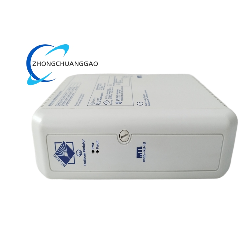
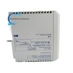
MTL 8922-RB-IS is a two-channel galvanically isolated intrinsically safe relay output barrier customized for discrete on/off digital control signal transmission. The module receives 24VDC logic switching commands delivered from PLC/DCS safe-side digital output card, converts non-IS control signals into intrinsically safe limited electrical output toward Zone 0/1/20 classified hazardous field equipment such as solenoid valves, flame arrestor actuators and field alarm beacons. Internal isolation architecture completely separates control room non-hazardous circuit and field intrinsically safe circuit to block cross-domain surge and ground loop interference. All field-facing electrical parameters comply with global ATEX and IECEx intrinsic safety certification limits, restricting maximum voltage, current and power output to hazardous side. Each channel integrates independent SPDT relay contact for passive field equipment switching control, factory fixed intrinsic safety parameters without field adjustable component modification, fully matching standard industrial 24VDC discrete control loop specification.
3. Technical Specifications
- Safe Side Control Supply Input: 18VDC ~ 32VDC DC rated input, nominal operating voltage 24VDC, built-in full circuit reverse polarity protection
- Channel Configuration: 2 completely independent electrically isolated single channels inside single housing, no electrical cross-coupling between two channels
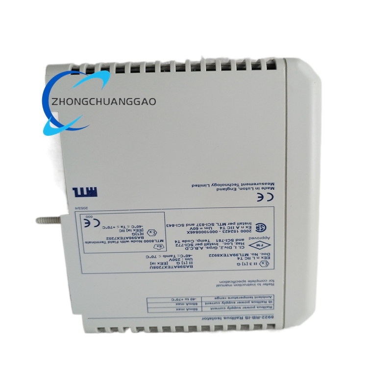
- Intrinsic Safety Rated Field Parameters: U₀=28VDC, I₀=115mA, P₀=0.82W, certified Ex ia IIB / Ex ia IIC intrinsic safety rating
- Internal Relay Specification: Per channel built-in SPDT single pole double throw electromagnetic relay
- Relay Contact Load Rating (Field IS Side): 3A @30VDC resistive DC load per single contact set
- Galvanic Isolation Withstand Voltage: 2500VAC for 60 seconds isolation between safe control circuit and hazardous field circuit
- Mounting Standard: Universal 35mm DIN top-hat rail clamping structure
- Overall Outer Dimension: Width 22.5mm × Height 115mm × Depth 98mm
- Continuous Working Ambient Temperature: -40°C ~ +70°C; sealed storage temperature: -45°C ~ +85°C
- Working Relative Humidity Range: 5%~95% non-condensing relative humidity across full rated temperature range
- Maximum Permitted Field Cable Parameters: Co=0.78μF, Lo=1.3mH per individual field channel
- Formal Certification: IECEx, ATEX, UL913 intrinsic safety approval, CE EMC industrial compliance certification
- Static No-Load Power Consumption: Max 2.9W under dual-channel full energized working status
4. Functional Features
- Dual fully isolated independent channel layout, each channel executes separate relay switching action without mutual signal interference.
- Hardware multi-stage limiting circuit permanently confines all field output electrical values within certified intrinsic safety rated U₀/I₀/P₀ limits for hazardous area installation compliance.
- Integrated bidirectional transient surge suppression components at both safe-side and field-side wiring terminals to absorb lightning induction and power switching transient overvoltage spikes.
- Clear physical terminal zoning printed on housing: SAFE terminal group exclusively for control room PLC wiring, FIELD terminal group dedicated for hazardous field equipment wiring to eliminate wrong cross wiring.
- Per-channel built-in status LED indicator fixed on front casing; LED illuminates synchronously once corresponding relay coil energizes and contact changes state.
- Zero onboard adjustable potentiometer or trimming component; all intrinsic safety and relay driving parameters are factory pre-calibrated for direct plug-and-play field replacement.
- Complete open/short circuit detection on safe-side input path; abnormal input status can be captured by upper DCS/PLC via original control circuit.
- Passive thermal design without built-in cooling fan; natural casing slit ventilation satisfies full-load continuous operation heat dissipation requirement.
5. Performance Parameters
- Relay pull-in action response time: ≤7ms from safe-side logic signal input to full mechanical contact closure completion
- Single relay mechanical no-load service lifespan: ≥10,000,000 switching cycles under rated ambient environment
- Relay electrical lifespan under full rated contact load: ≥95,000 continuous on-off switching operations
- Full unit overall MTBF value under standard industrial rated environment: 228000 continuous operating hours
- Internal driving circuit full-scale temperature drift coefficient: ≤11ppm/°C within -40°C~+70°C working temperature range
- Terminal screw repeated wiring fastening cycle life: ≥2000 tightening and loosening operations without thread sliding damage
- EMC compliance standard: EN61000-6-2 industrial environment electromagnetic immunity specification
6. Material Composition
- Main PCB Substrate: FR-4 high Tg flame retardant glass fiber printed circuit board with full immersion tin anti-oxidation surface coating, full SMT assembly technology.
- Outer Enclosure Shell: UL94-V0 flame retardant modified PA66 industrial engineering plastic with anti-aging and oil-resistant modified formulation.
- Wiring Terminal Components: Nickel-plated solid brass conductive inserts, zinc alloy anti-loose locking screws and PA66 flame retardant terminal insulation base.
- Internal Isolation Element: Epoxy encapsulated isolation transformer with high dielectric insulation layer between safe and hazardous circuit domains.
- Built-in Relay Assembly: Silver alloy contact sealed electromagnetic relay with high-temperature resistant bakelite coil skeleton.
- Onboard Passive Electronic Parts: AEC-Q200 grade TVS transient suppression diodes, X7R multilayer ceramic capacitors, precision metal film fixed resistors and certified intrinsic safety Zener components.
- Internal PCB Fixing Parts: High-temperature modified nylon positioning pillars for anti-vibration circuit board fixation inside plastic housing.
7. Structural Characteristics
- Compact single-width DIN modular integrated structure combining outer plastic casing and internal fixed PCB assembly.
- Internal PCB functional physical partition: Safe-side input driving circuit concentrated at one end, field-side IS relay output circuit arranged on opposite end, isolation transformer fixed in middle isolation zone to separate two electrical domains.
- Internal molded plastic isolation ribs separate two independent channel inner spaces to block channel-to-channel electromagnetic crosstalk during relay pull-in operation.
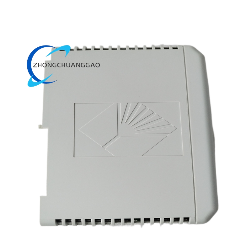
- Rear housing integrally formed DIN35 snap buckle for one-step clamping onto standard top-hat rail without extra fixing accessories.
- Front casing permanent high-temperature resistant ink silkscreen: part number marking, SAFE/FIELD terminal classification, IS certification parameter specification with anti-solvent corrosion property.
- Top and bottom of casing prefabricated tiny strip ventilation slits for passive natural convection heat dissipation.
8. Working Principle
Step 1: Safe Side Control Signal Receiving
24VDC on/off logic signal transmitted from control room PLC/DCS digital output terminal connects to module safe-side input terminal; internal power regulation circuit extracts stable driving power for isolation and relay drive loop.
Step 2: Isolated Signal Conversion
Input DC logic signal converts into modulated AC carrier via primary winding of internal isolation transformer; high insulation layer achieves complete electrical separation between safe and hazardous circuit domains.
Step3: Secondary Side Signal Restoration & Relay Drive
Transformer secondary winding recovers valid control signal after galvanic isolation, the restored voltage energizes corresponding channel internal relay coil to generate electromagnetic pull-in force.
Step4: Intrinsically Safe Field Output Switching
Energized relay drives SPDT contact state conversion; field-side output power is clamped by built-in IS limiting circuit within certified U₀/I₀/P₀ parameters before supplying to hazardous field connected solenoid or actuator equipment.
Step5: Status Indication Feedback
Corresponding channel LED indicator lights up synchronously following relay pull-in action to realize local on-site working status visualization.
Step6: Surge Fault Suppression
Transient abnormal overvoltage induced by field coil counter-electromotive force or grid fluctuation is absorbed by dual-side surge protection components to avoid internal circuit breakdown.
9. Advantage Highlights
- Dual-channel compact design reduces DIN rail occupied space versus two independent single-channel barriers and lowers spare part inventory cost for user maintenance management.
- Certified Ex ia IIC intrinsic safety rating supports installation matching hydrogen, acetylene-containing highest-grade hazardous classified field locations.
- High 2500VAC isolation rating thoroughly eliminates ground loop potential difference interference between control room earthing network and field hazardous grounding system to avoid false relay misoperation.
- Wide 18~32VDC safe-side input voltage range adapts industrial site backup battery voltage fluctuation under grid emergency power failure switching status.
- Factory full pre-certification and pre-calibration enables direct one-to-one field replacement without post-installation IS parameter verification or circuit debugging.
- Unified global DIN35 mounting standard fits all mainstream international brand industrial control cabinet internal rail layout specification.
- Dual-side integrated surge protection design effectively suppresses inductive load reverse electromotive force damage to internal core components and extends whole module service lifespan.
10. Applicable Industries
- Petrochemical Industry: Refinery, chemical synthesis workshop, hazardous chemical tank farm Zone1/Zone0 solenoid valve intrinsic safety drive control
- Natural Gas & LNG Industry: City gas pressure regulating station, LNG receiving terminal, long-distance gas pipeline valve chamber field actuator switching control
- Offshore Oil & Gas Industry: Offshore production platform, FPSO cabin combustible gas classified area on-site equipment interlock control
- Fine Pharmaceutical Industry: API synthesis workshop, organic solvent storage room explosion hazardous area auxiliary equipment on/off control
- Coal Chemical Industry: Coal gasification plant, coal-to-methanol production workshop Zone1 hazardous field discrete signal isolation barrier configuration
- Fertilizer Chemical Industry: Ammonia synthesis plant, urea production workshop toxic flammable gas area field solenoid valve safety driving
- Hazardous Waste Treatment Industry: Hazardous waste incineration plant flammable waste storage compartment field safety interlock equipment control
11. Model Series Affiliation
- Parent Product Series: MTL 8900 Series IS Isolated Relay Output Barrier Family
- Same Series Sibling Standard Models:
- 8921-RB-IS: Single-channel intrinsically safe relay output DIN barrier
- 8924-RB-IS: Four-channel compact IS relay output modular barrier
- Compatible Matching Host Equipment: Siemens, ABB, Honeywell, Yokogawa mainstream DCS/PLC 24VDC digital output cards; Field matching equipment: Intrinsically safe solenoid valve, flame damper actuator, field explosion-proof warning beacon
12. Installation Requirements
- Mounting Environment Standard: Install exclusively inside closed ventilated non-hazardous control cabinet; direct installation inside explosive classified hazardous field cabinet compartment is prohibited per intrinsic safety installation specification.
- DIN Rail Mount Specification: Snap rear integrated buckle onto standard 35mm top-hat DIN rail and press downward until full locking without loose displacement.
- Wiring Classification Regulation: Safe terminal wiring connects only to control room non-hazardous PLC/DCS circuit; field terminal wiring runs strictly toward Zone0/1/20 hazardous field equipment, cross wiring of two terminal groups is forbidden permanently.
- Field Cable Specification: Hazardous side field wiring must adopt intrinsically safe dedicated shielded twisted-pair cable; cable shielding layer single-point grounding only at control cabinet PE protective earth terminal.
- Heat Dissipation Clearance Requirement: Minimum 5mm vacant gap reserved between adjacent mounted modules for natural convection heat dissipation inside cabinet.
- Pre-install Confirmation: Verify field connected equipment inductance and capacitance parameters match module certified Co/Lo rating before wiring execution.
13. Use & Maintenance Precautions
- Strictly prohibit hot plugging/unplugging module under powered control loop status; live disassembly generates instantaneous surge voltage leading to permanent damage of internal isolation transformer and IS protection circuit.
- Never connect non-intrinsically safe overrated high voltage/current load into field-side terminals; over-specification access voids intrinsic safety certification and burns internal limiting components.
- All field wiring disassembly or modification work must be finished after cutting off full 24VDC control power supply from upper PLC/DCS side to avoid accidental short-circuit damage.
- Quarterly regular maintenance only uses dry lint-free cloth to wipe outer casing and terminal dust; alcohol, acetone and all organic solvent cleaning liquid direct contact with PCB and plastic housing is forbidden.
- Unused spare modules must be sealed inside anti-static shielding bag and stored under 10°C~35°C dry constant temperature environment; open-air damp or high-temperature long-term storage is prohibited.
- Field fault replacement only allows original factory certified genuine MTL 8922-RB-IS module; third-party refurbished or imitation substitute products cannot access certified intrinsic safety hazardous control loop.
- Avoid high-frequency inverter, arc welding and high-power RF equipment installed within 30cm distance of module installed control cabinet to prevent strong electromagnetic radiation triggering abnormal relay false action.



























Reviews
There are no reviews yet.