Product Brief Introduction
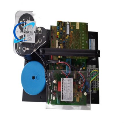
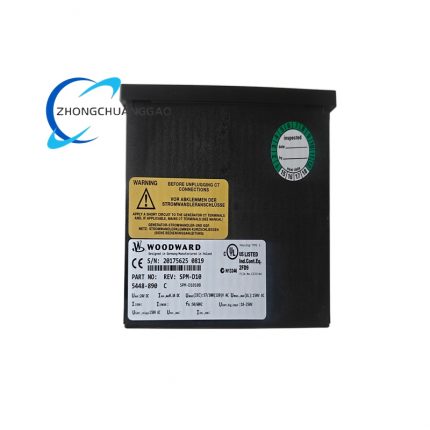
- This unit is a dedicated closed-loop digital speed governing controller engineered for diesel engines, gas engines, steam turbines and gas turbines, executes real-time rotational speed closed-loop regulation by collecting magnetic pickup speed feedback signal and outputting drive command to matched Woodward ProAct I/ProAct II fuel actuators to adjust engine fuel rack travel and intake air flow.
- The embedded high-output isolated sensor receiving circuit supports wide-amplitude passive magnetic pickup input, realizes seamless signal acquisition under strong field electromagnetic interference from engine ignition and high-power starter equipment.
- Every finished unit undergoes 72-hour continuous power aging test, full-range parameter calibration, alternating high-low temperature cycling verification and EMC anti-interference testing before factory delivery, holding UL, CE and DNV-GL marine industrial safety certification standards.
- It supports standalone constant-speed operation, droop parallel load sharing and base-load fixed-power control three core running modes; all internal control parameters can be configured via onsite terminal operation or upper computer debugging software through standard communication interfaces.
- Built-in full-set fault diagnosis and interlock protection logic, automatically triggers actuator stop command and fault code record once over-speed, under-speed, signal loss or abnormal power supply condition is detected during continuous running.
3. Technical Specifications (Core parameters marked in bold)
Power Supply Specification
- Nominal rated DC input working voltage:24VDC; continuous allowable fluctuation range:18VDC~36VDC, optional alternative AC power input range:85VAC~264VAC 50/60Hz
- Typical static operating power consumption:10W; maximum full-load peak power consumption ≤25W
- Internal power isolation withstand voltage:2200VAC/50Hz for 60s insulation withstand between power supply circuit and signal sampling circuit without breakdown.
Signal Input Specification
- Magnetic Pickup Speed Input Channel:2 independent isolated MPU channels, measurable input frequency range:1Hz~20kHz, corresponding configurable engine rotational speed span:20RPM~20000RPM
- Analog setpoint input:4 groups isolated 4~20mA DC analog input terminals, input fixed sampling resistance 250Ω per channel, supports external DCS/PLC remote speed setting signal access
- Auxiliary process input:2-channel Pt100 100Ω RTD temperature isolated input for engine coolant and exhaust temperature real-time collection
- Discrete digital input:8 groups optically isolated passive dry contact digital input with rated withstand voltage 5~48VDC for external shutdown, test mode and interlock switch signal access
Control Output Specification
- Main actuator drive output: ±200mA continuous proportional servo drive output specially matched with ProAct series electromechanical fuel actuator
- Auxiliary analog output:4 groups isolated 4~20mA DC configurable analog output for remote speed/load value transmission to upper monitoring system
- Relay fault output:4 groups SPDT electromagnetic relay output, single contact rated load:6A/250VAC for external alarm and breaker tripping control
Communication Specification
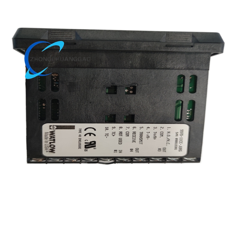
- Standard onboard communication interfaces: Dual redundant CAN FD bus compliant with ISO11898-1 standard, Modbus-RTU isolated RS485, isolated RS232 serial port
- RS485 maximum transmission wiring distance:1200m with double-core shielded twisted cable; RS232 fixed wiring limit within 15m.
- Dual CAN bus realizes bus redundancy switching automatically once single bus circuit fault occurs without controller operation interruption.
Environmental & Dimension Specification
- Continuous rated working ambient temperature range:-40℃~+85℃; certified long-term storage temperature range:-45℃~+95℃
- Working environment relative humidity:5%~95% non-condensing humidity; internal circuit condensation is prohibited during full-time continuous operation
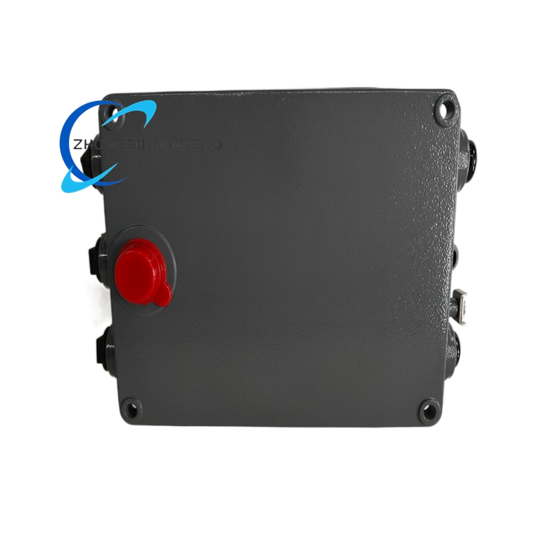
- Enclosure protection grade: IP66 / NEMA4X dustproof and splash-proof protection standard
- Overall outer dimension: 200mm(L)×150mm(W)×60mm(D); single unit net weight:1200g
- Mounting hole specification: Four symmetric fixed mounting holes with diameter 6.2mm reserved on enclosure side panel for cabinet bolt fastening installation.
4. Functional Features
- Adaptive PID closed-loop speed regulation function: Built-in self-tuning PID algorithm automatically matches engine inertia and load characteristic, completes proportional-integral-derivative parameter automatic optimization without manual onsite PID adjustment.
- Multi-unit parallel droop load sharing function: Realizes active power average distribution among multiple paralleled generator sets via CAN bus data interaction, configurable droop coefficient from 0%~10% according to grid operation requirement.
- Base-load fixed power control function: Locks genset output active power at preset fixed value, automatically adjusts engine fuel supply to counteract grid voltage and frequency fluctuation interference.
- Full-channel signal self-diagnosis function: Continuously monitors MPU open-circuit, analog input over-range, RTD wire breakage and power undervoltage fault; stores corresponding fault codes into nonvolatile memory meanwhile triggers relay alarm output.
- Remote parameter setting function: Real-time online parameter modification and operating data reading via Modbus-RTU/CAN bus from remote DCS and industrial SCADA monitoring platform.
- Multimode switching function: Supports Manual speed adjustment, Auto constant-speed, Test and Emergency Shutdown four fixed working mode free switching via front panel or external digital input terminal.
- Nonvolatile data storage function: All configured control parameters and historical fault records are saved in onboard EEPROM chip, all data is permanently retained after complete power cutoff without parameter loss.
5. Performance Parameters
Control Precision Index
- Static steady-state speed governing accuracy under constant 25℃ ambient temperature and full load variation: ≤±0.1%FS of rated engine set rotational speed
- Droop parallel load sharing deviation among multiple running units: ≤±2.5% of single unit rated active power under full-load rated operating condition
- Control stroke response speed: ≤50ms for 10%~90% full actuator stroke regulation command execution
Reliability Lifespan Index
- Factory certified continuous stable service lifespan: Minimum 68000 hours uninterrupted long-term running under standard ventilated closed cabinet installation environment
- Vibration durability standard: Pass IEC60068-2-6 10Hz~500Hz full frequency sweep vibration test with 5G peak acceleration without internal component loose and parameter drift
- Temperature cycling reliability: No functional failure and control precision drift after 1200 cycles of -40℃ ↔ +85℃ alternating high-low temperature aging test
Anti-interference Performance Index
- Allowable input DC power supply peak-to-peak ripple voltage: ≤18% of rated 24VDC input voltage without control output jitter and sampling data distortion
- EMC compliance standard: Fully conforms to IEC61000-6-2 industrial environment electromagnetic compatibility specification, keeps stable control performance nearby high-power contactor, frequency converter and engine ignition electromagnetic radiation equipment
6. Material Composition
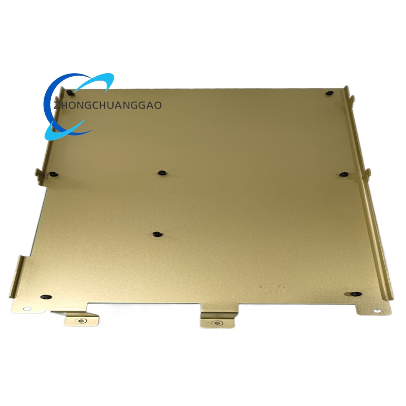
- Outer Enclosure Housing: Die-cast aluminum alloy shell with anti-corrosion electrostatic spray coating, meets IP66 protection mechanical strength requirement, integrated side mounting lug for fixed installation.
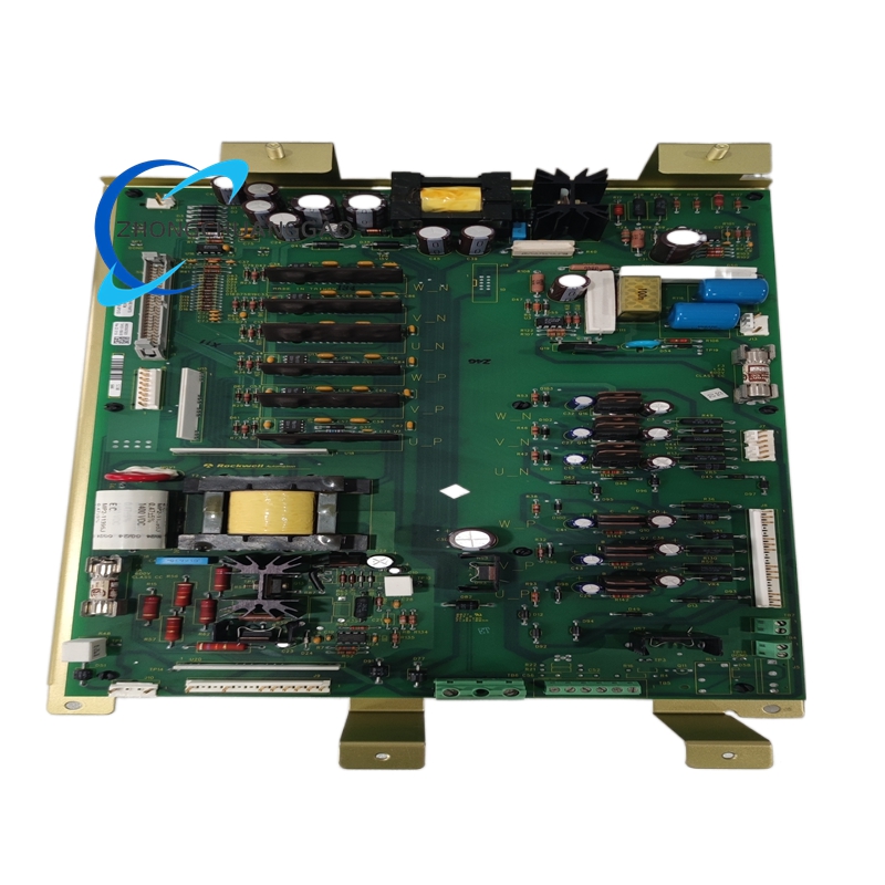
- Main Control PCB Board: FR-4 high-Tg flame retardant epoxy resin printed circuit board, internal copper conductor thickness 35μm, full-board coated with three-proof conformal paint against moisture, salt mist and chemical gas corrosion.
- Core Control Chip: Industrial wide-temperature grade 32-bit ARM embedded microprocessor with built-in hardware watchdog circuit to avoid program crash caused by strong electromagnetic surge.
- External Wiring Terminal: Glass fiber reinforced PA66 flame retardant plastic terminal base, tin-plated phosphor bronze alloy spring terminals for external field cable fastening connection.
- Internal Drive Component: High-precision isolated optocoupler chip for all input channel electrical isolation; silver alloy contact encapsulated relay for fault alarm output loop.
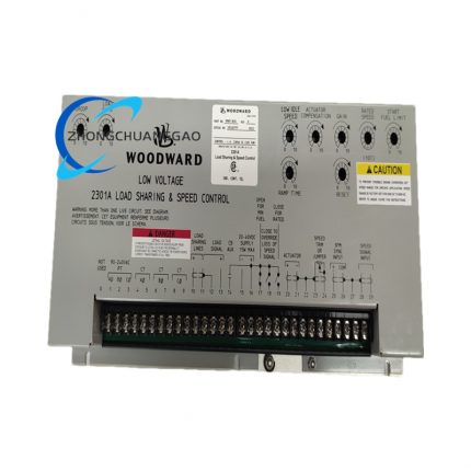
- Front Status Indicator: High-brightness industrial LED indicator lights with high-temperature resistant plastic fixed base for Power, Run, Communication and Fault status real-time display.
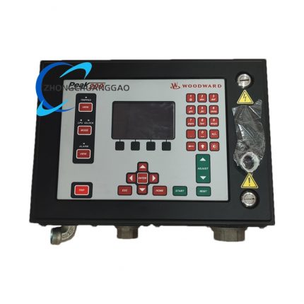
7. Structural Characteristics
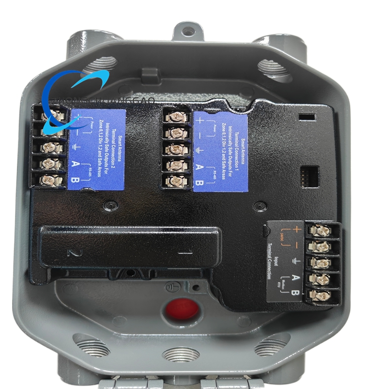
- Front-rear separated cavity layout: Front independent status indication area and rear centralized wiring terminal area separated by internal aluminum isolation partition, display circuit and signal circuit work inside mutually isolated closed space.
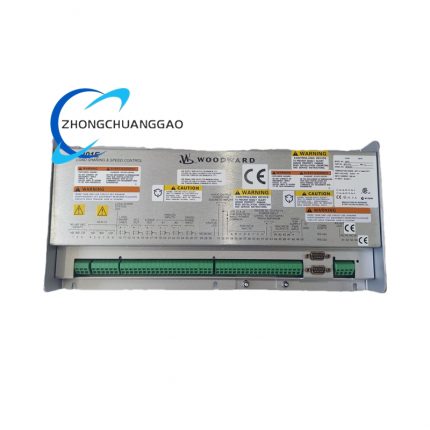
- Zoned rear terminal layout: All power input, MPU speed input, analog I/O, digital input and communication terminals are partitioned with printed functional marking on rear casing, classified into five independent wiring zones.
- Side integrated mounting lug structure: Four one-piece formed mounting lugs extend from left and right enclosure sides with pre-drilled fixed holes for direct bolt installation on cabinet metal panel without extra fixed accessories.
- Built-in passive natural heat dissipation structure: Multiple uniform strip-shaped heat dissipation slots distributed on upper and lower casing surface, rely on natural air convection to complete internal component heat dissipation without built-in cooling fan.
- Sealed front panel structure: Integral silicone rubber sealing ring embedded inside front panel edge to block dust and splash liquid infiltration into internal circuit space for IP66 protection realization.
8. Working Principle
- Power conversion stage: External 24VDC rated input power enters internal isolated switching power module, converted into stable 5VDC, ±15VDC and 24VDC multi-channel auxiliary power for main control chip, signal sampling circuit, communication module and relay drive circuit respectively.
- Speed signal acquisition stage: Passive magnetic pickup generates frequency pulse signal proportional to engine rotational speed, after entering high-output isolated receiving circuit, noise filtering and waveform shaping are completed before transmission to core microprocessor via high-speed AD conversion.
- Setpoint comparison operation stage: Microprocessor compares collected actual rotational speed value with remote analog setpoint or local manual setpoint value to calculate speed deviation quantity, invokes built-in adaptive PID algorithm to compute corresponding actuator drive output value.
- Actuator drive output stage: Calculated proportional control signal is converted into ±200mA DC continuous current output to matched ProAct fuel actuator, drives fuel rack to adjust engine fuel supply quantity for eliminating rotational speed deviation and realizing closed-loop constant speed control.
- Parallel load sharing stage: Under multi-unit grid-parallel running mode, real-time active power data is exchanged among multiple controllers via redundant CAN bus; each controller automatically modifies fuel output according to droop algorithm to complete average power distribution.
- Fault interlock protection stage: When sampling circuit detects abnormal speed out-of-limit, sensor wire breakage or power supply over/under voltage, internal hardware protection circuit immediately locks main actuator drive output, triggers corresponding fault relay action and stores fault information into nonvolatile memory chip.
9. Advantage Highlights
- Dual redundant CAN FD bus design avoids single communication line failure leading to whole control system halt, greatly improves system operation safety for critical uninterruptible power station projects.
- Built-in high-output wide-range MPU receiving circuit is compatible with multiple specification passive magnetic speed pickups, eliminates extra signal conditioning module procurement cost for field equipment upgrading transformation.
- Embedded automatic PID self-tuning function cancels complicated onsite manual PID parameter debugging work, shortens genset commissioning construction cycle drastically.
- Integrated droop + base-load dual control function satisfies standalone and grid-parallel two different genset operation requirements with single controller hardware without additional external auxiliary control module.
- IP66 full-sealed die-cast aluminum casing adapts to high-humidity, dusty and splash-prone severe onsite environment such as offshore platform and open-air drilling field.
- Complete UL/CE/DNV-GL certification supports global marine and offshore explosive hazardous area project bidding application range.
- Multi-group configurable analog and discrete I/O terminals reserve expansion space for subsequent auxiliary equipment interlock control modification without hardware replacement.
10. Applicable Industries
- Power Generation Industry: Distributed emergency standby diesel/gas genset constant speed control, industrial self-owned power plant multi-unit grid parallel load sharing management, commercial building UPS backup generator governing control.
- Oil & Gas Industry: Onshore oilfield drilling rig prime engine speed regulation, natural gas gathering station waste gas recovery gas engine control, offshore drilling platform fixed emergency genset governing system.
- Marine Engineering Industry: Ocean-going cargo vessel main propulsion diesel engine speed control, ship onboard auxiliary generator set parallel power distribution governing, offshore floating production platform backup genset control.
- Petrochemical Industry: Refinery waste heat recovery steam turbine speed regulation, chemical plant gas reciprocating compressor prime mover closed-loop governing control.
- Mining Industry: Underground coal mine fixed emergency power station genset control, open-pit mine mobile power vehicle multi-generator parallel load management.
11. Model Series Classification
- Parent Product Line: Woodward ProAct Model II Full Digital Speed Controller Product Family
- Same-series core derivative model classification:
- 9907-1280: Basic standard version without redundant CAN bus and RTD temperature input channel function
- 9907-1290: Standard enhanced full-function target model with dual redundant CAN FD, 2-channel RTD and complete parallel droop control function
- 9907-1290-EX: Explosion-proof customized variant with Class I Div.2 hazardous area certification for oil & gas explosive environment installation
- 9907-1300: High-power extended version with expanded I/O quantity for large-size heavy-duty gas turbine dedicated control
- Compatible matching accessory series: Full range Woodward ProAct I, ProAct II electromechanical fuel actuators, standard passive magnetic pickup speed sensors
12. Installation Requirements
- Panel Fixed Mount Specification: Align four enclosure side mounting lug holes with cabinet reserved mounting positions, use M5 standard stainless steel bolts for full fastening; reserve minimum 30mm free clearance space around controller periphery for natural heat dissipation air circulation.
- Wiring Specification: Main DC power supply wiring adopts ≥1.0mm² stranded copper cable; MPU speed signal and analog setpoint wiring uses double-core shielded twisted cable with shielding layer single-end grounded at cabinet protective earth bar; strong-current power wiring and weak-current signal wiring keep minimum 22mm separation spacing to prevent electromagnetic coupling interference.
- Cabinet Environmental Restriction: Install inside closed ventilated control cabinet, keep away from frequency converter, large AC contactor and engine starter strong electromagnetic radiation components; avoid direct liquid splash and high-temperature heat source baking on controller casing.
- Pre-power-on Inspection Rule: Complete full wiring continuity and short-circuit inspection for power, MPU and analog terminal before initial energization; restore factory default parameters then finish onsite engine matching parameter configuration after controller power-on initialization.
- Protective Grounding Specification: Connect controller reserved grounding terminal to cabinet dedicated protective earth busbar with ≥1.5mm² copper grounding wire; series grounding with other high-power electrical equipment grounding terminal is forbidden.
13. Usage Precautions
- Power-on Preheating Regulation: After connecting rated 24VDC working power supply, maintain controller idle energized preheating for minimum 3.5 minutes before formal speed calibration and load debugging to stabilize internal AD sampling circuit measurement precision.
- Parameter Modification Regulation: Core PID parameter, droop coefficient and protection threshold modification can be completed under live running state; one no-load speed stability test must be executed immediately after parameter setting completion to verify modification validity.
- Anti-liquid Infiltration Regulation: Prevent engine lubricating oil, cleaning water, corrosive chemical solvent from splashing onto rear wiring terminal region; liquid infiltration will lead to terminal short-circuit and internal circuit permanent burnout.
- Long-term Idle Storage Specification: Remove all external connecting cables after dismounting for storage over 30 days, place unit inside original factory sealed anti-static carton under 10℃~35℃ dry indoor environment away from corrosive volatile gas and dust accumulation.
- Live Operation Forbidden Regulation: Strictly prohibit live plugging/unplugging rear wiring terminal block and communication bus connector; live plug action generates instantaneous surge voltage to damage internal microprocessor and communication chip permanently.
- Periodic Maintenance Regulation: Complete annual routine maintenance under full power-off state including fastening loose terminal screws, cleaning casing surface and terminal dust with dry compressed air; damaged replacement parts must adopt original Woodward certified exclusive accessories only.

")
")


Reviews
There are no reviews yet.