Model Series
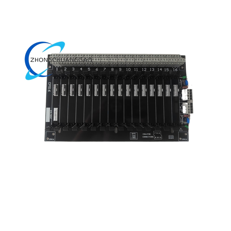
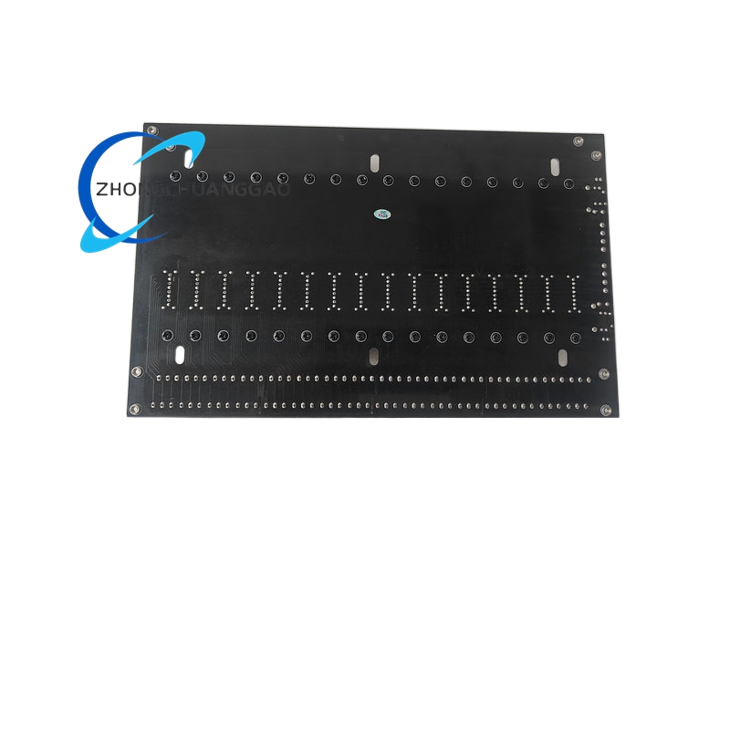
MTL CPS Standard Safety Barrier Baseplate Series
Technical Specifications
- Slot Capacity: 16 independent plug-in barrier module slots
- Rated Supply Voltage: 24 V DC nominal, operating range 19.2 V DC – 28.8 V DC
- Power Distribution: Dual redundant power bus rails integrated into baseplate PCB
- Termination Type: Screw-clamp terminal blocks for safe-area field circuit wiring
- Maximum Per-Slot Current: 150 mA continuous per barrier module slot
- Bus Isolation: 2.5 kV AC isolation between field circuit bus and power supply bus
- Mechanical Mounting: Compatible with standard 35 mm DIN rail and surface panel mounting brackets
- Overall Dimensions: 310 mm (L) × 110 mm (W) × 65 mm (H)
- Total Weight: 0.62 kg
Performance Parameters
- Power Bus Parallel Capacity: Multiple CPS16 baseplates may be wired in parallel for shared redundant 24 V DC power supply
- Terminal Torque Rating: 0.8 N·m maximum screw terminal tightening torque
- Insulation Resistance: ≥ 1000 MΩ between power bus and field signal bus at 500 V DC test voltage
- Operating Temperature Range: -20 °C to +60 °C
- Storage Temperature Range: -40 °C to +85 °C
- Relative Humidity Tolerance: 5% – 95% RH non-condensing continuous operation
Material Composition
- Baseplate PCB: Flame-retardant FR-4 V0 rated printed circuit board
- Terminal Block Housings: High-temperature thermoplastic polyamide PA66 flame resistant material
- Conductive Bus Bars: Tin-plated copper alloy power distribution rails
- Mounting Frame: Galvanized cold-rolled steel DIN rail clip bracket
- Terminal Screws: Nickel-plated steel anti-corrosion fasteners
- Labeling Cover: Transparent polycarbonate removable channel identification cover
Structural Features
- Uniform 16 independent interchangeable slots; all MTL intrinsic safety barrier models install in any slot position without fixed ordering requirements
- Dual parallel redundant 24 V DC power rails integrated into PCB to support dual power supply redundancy architecture
- Screw-clamp terminal blocks segregate safe-area power wiring and hazardous-area field signal wiring
- Removable transparent plastic labeling cover for slot channel number identification and wiring documentation
- Integrated DIN rail clip mounting foot for direct snap-on installation to standard 35 mm DIN mounting rails
- Ground bus terminal integrated at baseplate edge for system protective earth connection
Working Principle
- External redundant 24 V DC industrial power supply connects to baseplate power bus screw terminals; dual parallel power rails provide failover power feed to all 16 module slots.
- Each installed intrinsic safety barrier module draws regulated power from shared baseplate power bus via edge card connector contacts.
- Hazardous area field sensor wiring terminates to dedicated screw-clamp signal terminals, routed through PCB isolation circuits to barrier module signal pins.
- Internal PCB isolation barriers separate high-power supply circuits from low-level field measurement signal circuits to maintain intrinsic safety certification compliance.
- Protective earth ground bus connects all module chassis grounds to single unified grounding terminal for electrostatic discharge and surge protection.
Core Function Features
- 16 universal interchangeable slots supporting mixed MTL safety barrier models on single baseplate assembly
- Dual redundant 24 V DC power distribution bus for uninterrupted barrier module operation during single power supply failure
- Screw-clamp industrial wiring terminals eliminating loose wiring contact failure risks
- Full intrinsic safety circuit isolation maintaining ATEX / IECEx hazardous area certification compliance
- Integrated unified grounding bus for all installed safety barrier modules
- Removable transparent labeling cover for channel identification and wiring traceability
- Multi-mount compatibility: DIN rail snap-on and surface panel bolt mounting bracket support
Advantage Highlights
- Single baseplate consolidates 16 separate safety barrier installations to reduce cabinet wiring complexity and space occupation
- Redundant power bus design eliminates need for separate power distribution wiring for each individual barrier module
- Mixed-model barrier slot compatibility allows flexible combination of analog input, digital input and relay output safety barriers
- Integrated isolation circuits maintain full hazardous area intrinsic safety certification without additional external isolation hardware
- DIN rail snap-on mounting enables rapid cabinet assembly and reconfiguration during plant commissioning
- Parallel baseplate power bus capability supports large-scale distributed hazardous area measurement systems
Applicable Industries
Oil & Gas Refineries, Petrochemical Process Plants, Pharmaceutical Batch Manufacturing, Mining Hazardous Gas Monitoring, Fertilizer Chemical Production, Liquefied Natural Gas Terminals, Hazardous Waste Treatment Facilities
Installation Requirements
- Mount baseplate horizontally onto standard 35 mm DIN rail inside classified safe-area control cabinet
- Secure baseplate ground terminal to cabinet protective earth bus with minimum 2.5 mm² copper grounding cable
- Torque all power and signal terminal screws to 0.6–0.8 N·m specified torque range
- Maintain minimum 20 mm vertical clearance above and below baseplate for cabinet air circulation
- Route hazardous area field wiring and safe-area power wiring into separate dedicated terminal blocks with no cross-wiring
- When paralleling multiple CPS16 baseplates, connect power bus terminals in daisy-chain parallel configuration with adequate gauge power cables
Operation & Maintenance Precautions
- Do not install non-MTL uncertified barrier modules into baseplate slots; intrinsic safety certification will be voided
- Ensure cabinet ambient temperature never exceeds +60 °C continuous operating limit to prevent terminal insulation degradation
- Tighten all terminal block screws every 6 months to compensate for thermal cycling induced wire loosening
- Prevent dust, oil vapor and chemical condensation accumulation on baseplate PCB and terminal contacts
- Disconnect both redundant power supply feeds before removing or inserting barrier modules to avoid live contact arcing
- Do not modify baseplate PCB trace routing or add external wiring taps to integrated power bus rails
- Replace cracked or damaged terminal block plastic housings immediately to maintain flame resistance and isolation integrity



























Reviews
There are no reviews yet.