Technical Specifications
- Measuring Voltage Input Range: 90VAC ~ 480VAC 3-phase / single-phase universal
- Frequency Operating Band: 45Hz ~ 65Hz (50Hz / 60Hz factory configurable)
- Supported Generator Power Rating: 10kW ~ 3000kW genset units
- DC Control Supply Voltage: 12VDC / 24VDC battery dual support (9V ~ 36VDC continuous input tolerance)
- Control Algorithm: Dual PID closed-loop regulation for speed (governor) and voltage (AVR)
- Communication Interfaces: RS232, RS485, Ethernet TCP/IP, CAN bus
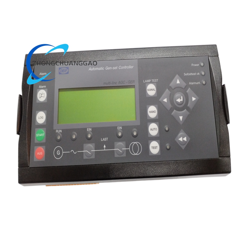
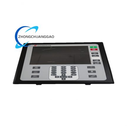
- Front Panel Display: Backlit LCD multi-line operation screen with physical navigation keys
- Digital Input Channels: 32 multi-function programmable binary inputs
- Digital Relay Output Channels: 16 potential-free relay outputs (5A resistive contact rating)
- Operating Temperature Range: -20°C ~ +70°C
- Storage Temperature Range: -40°C ~ +85°C
- Front Panel Protection Grade: IP65 dust & splash resistance
- Rear Terminal Housing Protection: IP20
- Physical Dimensions: 225mm (W) × 175mm (H) × 100mm (D)
- Net Weight: 3.0kg
- Certifications: CE, UL, IEC 60204-1 marine & industrial safety certified
Functional Features
- Four core operation modes: MAN Manual, AUTO Automatic, TEST Load Test, BLOCK Maintenance Lock
- Complete AMF logic: Mains loss detection, auto genset startup, mains/genset synchronization, load transfer, cool-down shutdown upon mains restoration
- Multi-unit parallel load sharing with reactive & active power balance regulation for up to 32 parallel gensets
- Full electrical protection suite: Overvoltage, undervoltage, overfrequency, underfrequency, reverse power, overload, short circuit, negative sequence, ground fault, overcurrent
- Event data storage: 150 operation event logs, 30 historical fault alarm logs with timestamp recording
- Service interval reminder system with two independent maintenance timers
- Synchronization checker with adjustable phase angle, voltage difference and frequency window thresholds
- Password tiered access control: Operator, Technician, Administrator three permission levels
- Remote monitoring & parameter modification via Ethernet Modbus TCP or RS485 Modbus RTU
- Real-time metering display: kW, kVAR, kWh, voltage, current, power factor, engine RPM, battery voltage, coolant temperature
Working Principle
32-bit industrial microprocessor continuously samples generator and mains voltage/current signals via isolated voltage/current transformers. Real-time comparison algorithms calculate frequency, phase angle and voltage differential to execute soft synchronization logic. PID control loops output analog/digital signals to engine governor and automatic voltage regulator to stabilize genset output. All fault threshold parameters are stored in non-volatile flash memory; upon abnormal electrical condition, controller immediately triggers relay outputs to activate circuit breaker trip, engine shutdown and alarm signals while logging fault timestamp data.
Material & Structural Composition
- Front Panel: Reinforced ABS plastic with anti-scratch matte coating, silicone waterproof key membrane
- Rear Enclosure: Die-cast aluminum alloy housing with corrosion-resistant powder coating
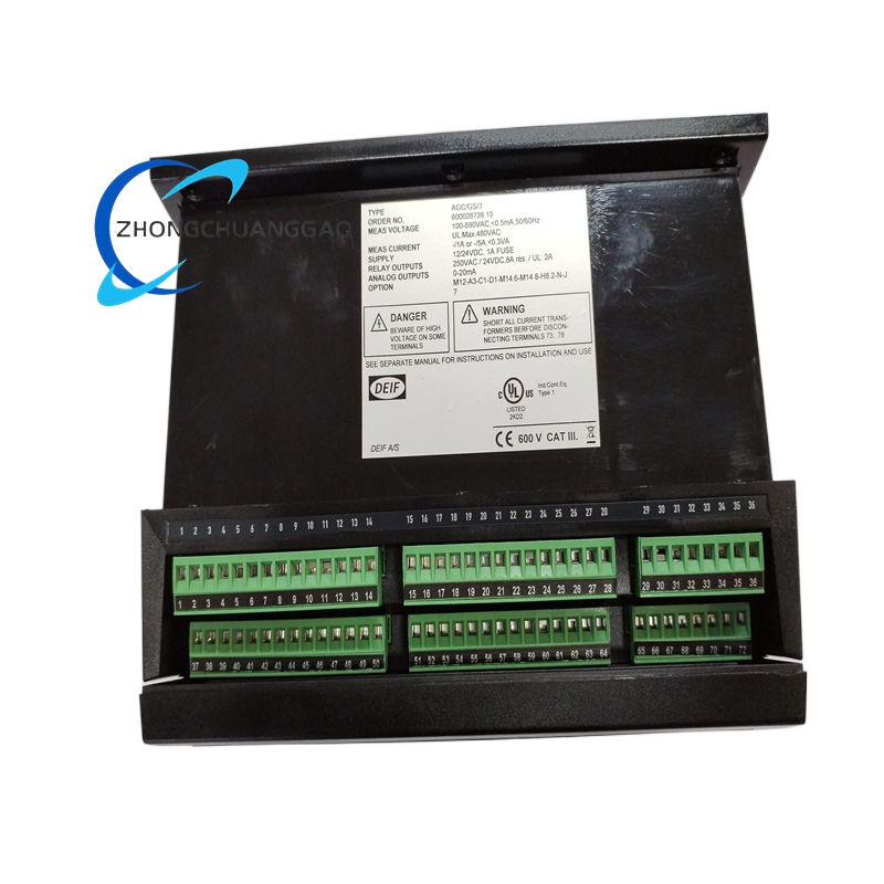
- Terminal Blocks: Green spring-clamp screw terminals with copper conductive inserts
- Internal Circuit Board: Multi-layer FR4 PCB with conformal coating for humidity & dust resistance
- Display Module: Industrial LCD with LED backlight, wide temperature liquid crystal panel
Advantage Highlights
- Single hardware unit supports standalone genset, mains parallel, multi-generator island parallel applications without hardware modification
- Wide DC battery supply tolerance eliminates dedicated power supply modules for genset battery cabinet integration
- IP65 front panel enables installation on outdoor generator control cubicle doors without additional protective covers
- Conformal coated internal PCB maintains stable operation in high-humidity marine, mining and offshore environments
- Fully configurable I/O mapping eliminates external auxiliary relays for custom genset wiring logic
- Built-in real-time clock with backup supercapacitor retains log timestamps during temporary power loss
Applicable Industries
Data center backup power plants, commercial building standby generators, marine vessel power systems, oil & gas offshore gensets, mining mobile power units, hospital critical backup power, solar/wind hybrid power storage stations
Installation Mandatory Requirements
- Cutout panel mounting standard industrial cabinet door cutout dimensions 210mm × 160mm
- Maintain minimum 50mm clearance behind controller for wiring ventilation and heat dissipation
- Separate high-current power transformer wiring from low-voltage communication cabling by minimum 10cm distance
- Connect dedicated 12V/24V lead-acid battery power supply; avoid shared power with engine starter circuits
- Max operating altitude 2000m; derate protection response speed by 10% per 1000m elevation over threshold
Operation & Maintenance Precautions
- Conduct annual LCD backlight brightness inspection to prevent screen fading
- Download event logs quarterly for equipment failure trend analysis
- Avoid controller exposure to direct high-temperature engine exhaust heat radiation
- Calibrate voltage/current measuring transformers every two years to maintain metering accuracy
- Do not disconnect DC power supply during parameter upload/download to prevent flash memory corruption



























Reviews
There are no reviews yet.