Core Technical Specifications
- Main Mains Power Input: AC 100 V 50/60 Hz single-phase supply
- Control Command Input Signal: 0–10 V DC differential analog voltage input
- Input Impedance: 10 kΩ balanced differential input impedance
- Rated Continuous Output Current: ±1 A for 10 Ω proportional solenoid coil load
- Peak Short-Term Output Current: ±2 A maximum peak current
- Internal Dither Frequency: 200 Hz adjustable amplitude dither signal to eliminate valve stick-slip friction
- Maximum Gain Rating: 1 A / 5 V input signal proportional gain
- Temperature Drift Characteristic: Maximum 0.2 mA / °C output current drift
- Operating Ambient Temperature Range: 0 °C to +50 °C non-condensing
- Ingress Protection Class: IP20 cabinet indoor installation only
- Physical Dimensions: 120 mm (H) × 80 mm (W) × 45 mm (D)
- Net Weight: 0.42 kg
Functional Features
- Differential DC voltage input circuit rejects common-mode industrial electrical noise
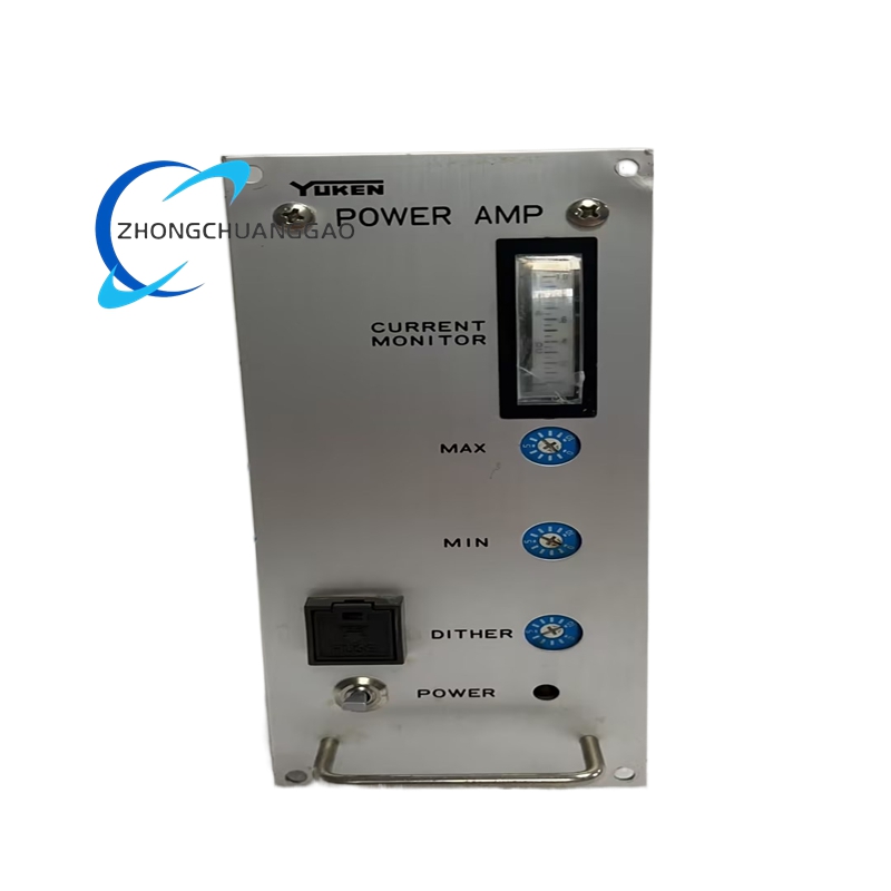
- Adjustable internal dither signal amplitude to eliminate proportional valve spool static friction hysteresis
- Front-panel potentiometers for proportional gain, dead-band compensation, and ramp acceleration/deceleration time tuning
- Built-in short-circuit and overcurrent output protection with automatic fault current limiting
- Bi-directional output current enables forward/reverse proportional valve spool position regulation
Working Principle
0–10 V DC analog command signal enters the differential input stage, which subtracts external feedback valve spool position signal to generate a deviation voltage. The deviation voltage drives a pulse-width modulation power stage that generates regulated bi-directional output current matched to the 10 Ω proportional solenoid coil load. An integrated 200 Hz dither signal superimposes onto the output current to continuously vibrate the valve spool and eliminate static friction stick-slip effect. Adjustment potentiometers modify proportional gain and signal ramp timing to tune hydraulic loop dynamic response characteristics.
Material & Structural Characteristics
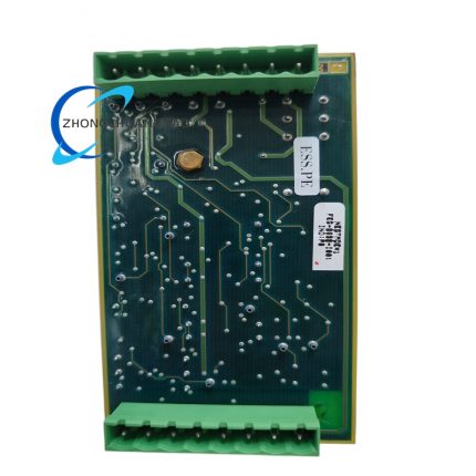
- Main circuit board: FR-4 flame-retardant PCB with surface-mount power semiconductor components
- Outer housing: ABS flame-resistant industrial plastic black enclosure with vertical ventilation slots
- Adjustment components: Sealed dust-proof rotary potentiometers with metal adjustment shafts
- Wiring terminals: Screw-type brass terminal blocks with anti-loosening spring washers for power, input, and load wiring
Core Advantages & Highlights
- Differential input circuit delivers superior noise rejection in heavy industrial hydraulic machine environments
- Adjustable dither amplitude eliminates proportional valve hysteresis for ultra-precise flow/pressure regulation
- Full overcurrent and short-circuit protection prevents permanent proportional solenoid coil damage
- Front-panel accessible tuning potentiometers enable on-site hydraulic loop response calibration without disassembly
- Optimized circuit design exclusively matched to 10 Ω standard YUKEN proportional valve coils
Applicable Industries
Injection molding machine hydraulic control, metal stamping press proportional hydraulic systems, CNC machine tool feed drive hydraulic circuits, die casting machine pressure control loops, construction machinery hydraulic proportional valve drive systems
Installation Mandatory Requirements
- Mount vertically inside hydraulic control cabinet with minimum 20 mm top/bottom ventilation clearance
- Separate high-current valve load wiring from low-level analog command signal wiring by minimum 15 cm distance
- All analog command wiring must use shielded twisted-pair cable with single-point shield grounding
- Install mains surge protection device on the AC 100 V power input terminal to suppress grid voltage transients
- Complete gain and ramp time calibration after full wiring connection before hydraulic system pressurization
Operation & Maintenance Precautions
- Do not connect solenoid coil loads with resistance values outside the 9–11 Ω design operating range
- Keep amplifier housing free of hydraulic oil mist contamination to prevent internal circuit short-circuit failure
- Avoid ambient humidity exceeding 80% non-condensing to prevent PCB trace corrosion
- Disconnect AC 100 V mains power before adjusting front-panel calibration potentiometers
- Replace internal power switching semiconductors immediately upon persistent overcurrent fault activation



























Reviews
There are no reviews yet.