Product Brief Introduction
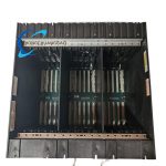
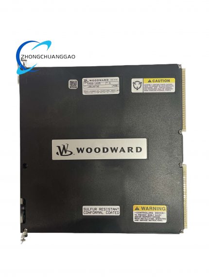
- Woodward 5453-759 is factory-calibrated standard VME bus chassis independently developed for Woodward MicroNet Plus distributed turbomachinery control system, serving as core mechanical mounting and power/data bus transfer carrier for all internal functional modules.
- This chassis integrates built-in high-speed multi-layer printed backplane, standardized VME slot positioning structure and full-system DC24V power distribution circuit, supporting hot-swap online replacement of CPU, analog/digital I/O, communication and power supply modules under system live running state.
- The whole product passes factory full-load aging test, EMC anti-interference certification and insulation withstand voltage inspection before delivery, each unit carries exclusive serial number for full lifecycle spare part traceability management.
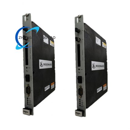
- It supports both Simplex single system layout and TMR triple modular redundant control system configuration, which is the standardized cabinet core rack applied on gas turbine, steam turbine and large reciprocating engine governing control unit.
3. Technical Specification
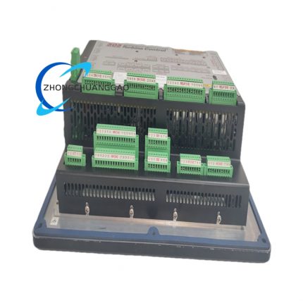
- Total available installation slot quantity: 14 universal standard VME64X slot positions, all slots share unified backplane bus resource
- Rated distributed bus working voltage: DC 24V, allowable input fluctuation range DC20.4V ~ DC27.6V, bus rated total output load current: 28A full chassis total rating
- Backplane bus standard compliance: Strictly follows ANSI/IEEE 1014 VME64X industrial bus specification, parallel data bus bandwidth fixed at 40MB/s per slot
- Overall external dimension: 482.6mm(W) × 228.6mm(H) × 101.6mm(D), standard 19-inch industrial rack installation outline size
- Net single unit weight: 1.36kg without any loaded inner functional modules
- Enclosure protection grade after cabinet installation: IP20 compliant with IEC60529 standard
- Continuous working ambient temperature range: -20℃ ~ +70℃; extreme storage temperature: -40℃ ~ +85℃
- Allowable working relative humidity scope: 5%RH ~90%RH non-condensing, zero corrosive gas environment required for long-term stable operation
- EMC certification standard: IEC61000-6-2 industrial environment anti-electromagnetic interference certification passed by factory test
- Vibration endurance specification: Comply with IEC60068-2-6 standard, continuous anti-vibration 3g RMS within 10Hz~500Hz frequency band during equipment normal operation
4. Functional Features
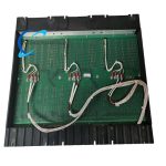
- Built-in integrated multi-layer backplane realizes centralized DC24V power distribution and full VME bus signal interconnection among all 14 slots, eliminating external discrete wiring between each internal module.
- Every slot adopts standard VME64X spring-type connector structure, supports hot-plug module replacement without overall system power cut, ensuring uninterrupted operation of redundant control system.
- Reserved independent grounding copper bar inside chassis frame, centralized convergence of all modules protective ground signal to avoid scattered ground loop interference in control cabinet.
- Fixed partition layout design for chassis inner space, left area reserved for power module installation, middle and right area for CPU, I/O and communication card sequential arrangement according to factory standard layout rule.
- Backplane embedded surge suppression circuit on each power pin, absorbing instantaneous surge voltage transmitted from cabinet power supply side to protect all loaded control modules from overvoltage breakdown damage.
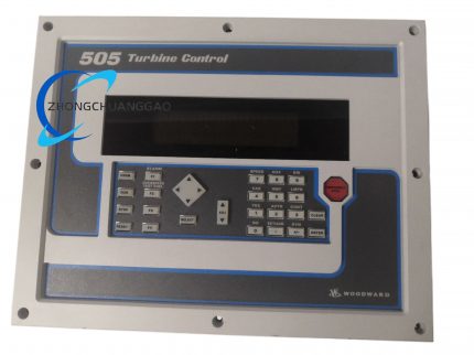
- Front panel of chassis reserved marking blank area for manually labeling slot serial number and corresponding module part number, convenient for daily maintenance and module fault positioning work.
- Two installation modes available: standard 19-inch front rack fixed mounting and rear cabinet wall screw fixed installation to match different cabinet internal layout requirements.
- Built-in reserved auxiliary wiring routing groove on chassis upper and lower edges for external shielded signal cable regular arrangement, preventing messy wiring from causing electromagnetic crosstalk between signal lines.
5. Performance Parameter
- Backplane single-slot power supply voltage fluctuation: ≤±1%FS under full chassis rated 28A load condition at 25℃ standard ambient temperature
- Slot-to-slot bus signal crosstalk attenuation: ≥55dB within 0~20MHz bus signal frequency range
- Backplane copper foil insulation resistance between power layer and signal layer: ≥1500MΩ tested with DC500V megohmmeter at normal ambient environment
- Continuous long-term drift of backplane power distribution circuit: ≤0.03%FS per 24-hour full-load uninterrupted running under constant temperature condition
- Hot-swap instantaneous voltage drop during single module plugging: ≤0.8V on chassis main DC24V bus without triggering system undervoltage protection action
- Full chassis backplane withstand voltage: AC1500V/1min no breakdown between power bus and chassis metal ground frame
- Bus signal transmission delay between arbitrary two slots: ≤12ns fixed transmission latency at rated operating temperature
6. Material Composition
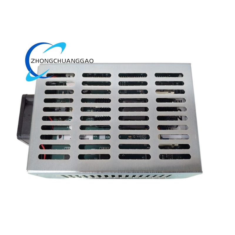
Outer Chassis Frame & Shell Structure
- Main chassis frame: Cold-rolled SPCC steel plate with black matte epoxy anti-corrosion electrophoretic coating, plate thickness 1.5mm; four fixed installation lug pieces adopt 2.0mm thick steel stamping forming process.
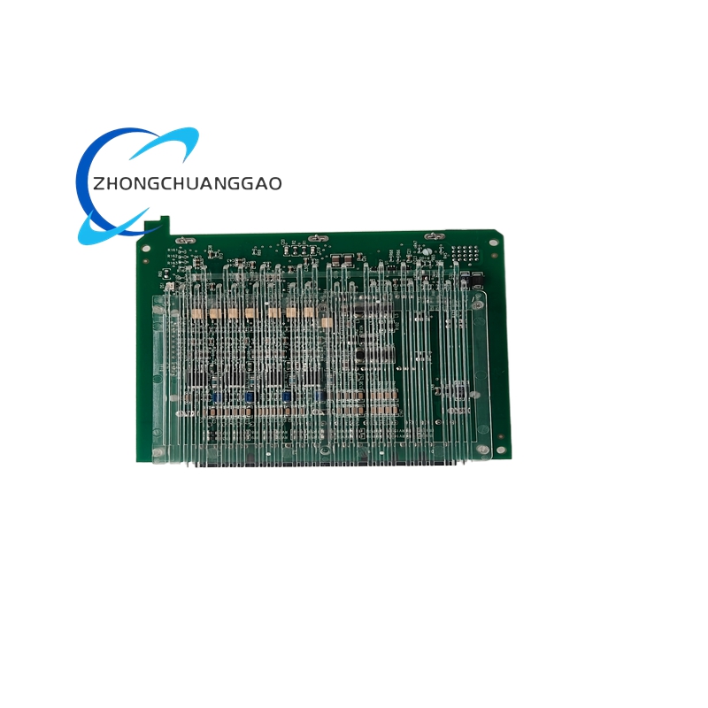
Internal Backplane PCB Core Board
- Backplane substrate material: FR-4 TG170 high-temperature flame retardant epoxy glass fiber board, total 8-layer laminated PCB structure; inner layer copper foil thickness 35μm for power layer and 18μm for signal layer; board surface lead-free HASL anti-oxidation treatment.
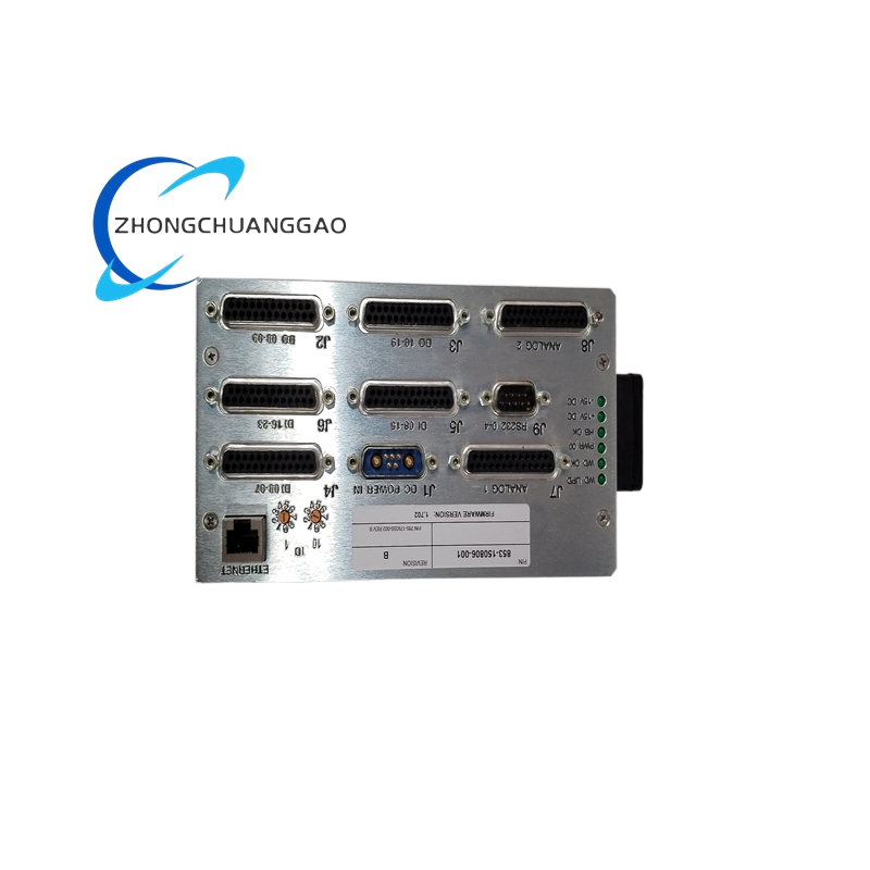
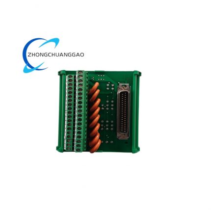
Slot Connector & Conductive Components
- VME slot female connector housing: UL94-V0 grade reinforced PA66 glass fiber filled nylon insulating material; internal contact pins: phosphor bronze raw material with full surface gold plating of 0.8μm thickness for anti-oxidation stable conduction.
- Internal grounding bus bar: T2 pure copper strip with nickel plating anti-corrosion surface processing; fixed locking screws for frame assembly: SUS304 stainless steel miniature fasteners.
Auxiliary Internal Accessories
- Built-in surge suppression components: SMD packaged TVS diode and ceramic discharge tube fixed on backplane edge; internal routing insulation separators: modified PP high-temperature resistant plastic injection molding material.
7. Structural Characteristics
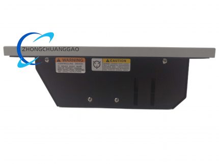
- Overall split three-section integrated structure: front mounting ear rack frame, middle backplane fixed cabin, rear closed dustproof back cover, three parts locked by evenly distributed stainless steel anti-loose screws into integral unit.
- 14 VME slots arranged in single horizontal equal-spacing array inside chassis inner cavity, each slot corresponds to fixed silk-screen slot number printed on backplane edge for installation identification.
- Four symmetrical mounting lugs reserved on chassis front left and right sides with pre-opened standard M6 installation screw holes matching 19-inch rack mounting specification.
- Independent closed back cover installed at chassis rear side with removable buckle structure, dismountable without tools for convenient backplane maintenance inspection.
- Internal chassis wall pasted black EPDM foam damping strip to reduce vibration transmission from cabinet rack to backplane PCB during equipment operation.
- Bottom side of chassis reserved long strip ventilation gap for natural heat dissipation of loaded modules, avoiding overheating accumulation inside closed chassis inner cavity.
8. Working Principle
- External cabinet isolated regulated DC24V power supply is connected to chassis reserved main power terminal, power enters backplane centralized power distribution layer and distributes stable DC24V working voltage to all 14 slot power pins synchronously.
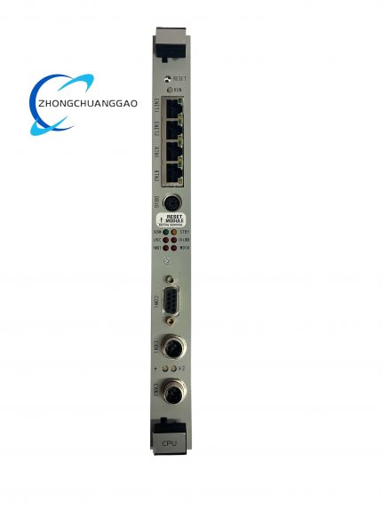
- After CPU module and each functional I/O/communication module insert into corresponding VME slot, metal contact pins of module rear connector fully dock with backplane gold-plated pins to complete electrical conduction connection of power and VME bus signal.
- CPU module sends control command and digital data through backplane VME parallel bus to each I/O and communication module; field collected analog/digital feedback signals are uploaded to main control CPU via reverse bus transmission path to complete closed-loop data interaction.
- When single internal module needs online replacement, hot-swap circuit on backplane automatically suppresses instantaneous power surge during plugging action, other remaining modules keep normal power supply and bus communication without system shutdown.
- All module protective grounding leads converge onto chassis internal copper ground bus, then uniformly connects to cabinet PE protection ground bar to realize unified equipotential grounding and eliminate common-mode interference induced by ground potential difference.
- Built-in backplane surge absorption components automatically clamp abnormal overvoltage peak on power bus when external power supply instantaneous surge occurs to protect all inserted functional modules from overvoltage damage.
9. Advantage Highlights
- Standard VME64X bus unified design achieves full compatibility with all Woodward MicroNet Plus series CPU, I/O, communication and power modules, zero installation mismatch error during module assembly.
- Integrated centralized backplane structure removes complicated discrete inter-module wiring, greatly reduces cabinet internal wiring quantity and subsequent circuit fault occurrence probability.
- Full hot-swap supporting design realizes single faulty module online replacement without whole control system outage, improving overall equipment operation availability for power station uninterruptible production scene.
- Wide-temperature grade raw material selection of backplane and chassis enables stable continuous operation from -20℃ to +70℃ without additional cabinet forced cooling fan configuration under standard industrial cabinet environment.
- Complete factory serial number traceability management of each chassis ensures spare part inventory accurate matching and after-sale maintenance component consistency for all delivered equipment units.
- Dual installation mode satisfies diversified cabinet layout demands, shortens on-site equipment cabinet transformation construction period during control system upgrading and reconstruction project.
- Certified IEC industrial EMC design makes chassis applicable for strong electromagnetic interference working site near high-voltage transformer and large frequency converter without extra external shielding accessory matching.
10. Applicable Industries
- Thermal Power Generation Industry: Steam turbine, gas turbine, diesel generator set governing control cabinet core carrier for MicroNet Plus control system module centralized installation.
- Oil & Gas Industry: Offshore platform large compressor control cabinet, natural gas pipeline pressurization unit turbomachinery control system rack assembly application.
- Marine Propulsion Industry: Large cargo vessel main engine speed control cabinet, marine auxiliary gas turbine governing system core chassis installation matching DNV-GL marine equipment application standard.
- Petrochemical Refining Industry: Refinery heating furnace blower, large reciprocating compressor safety interlock control system internal module centralized installation carrier.
- Hydropower Equipment Industry: Large hydro-turbine governor control cabinet core rack for core CPU and analog signal acquisition I/O module layout installation.
- Industrial Heavy Machinery Industry: Large industrial gas engine unit, turbocharger test bench closed-loop control system core control chassis configuration.
11. Model Series Classification
- Base standard model: 5453-759 (Original factory standard bare chassis without pre-installed internal modules, default bare backplane configuration)
- Derivative variant 1: 5453-759-C (PCB backplane full conformal coated customized version for high-humidity coastal and chemical corrosive gas working environment)
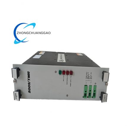
- Derivative variant 2: 5453-759-T (Pre-installed factory matched full set redundant power supply module chassis assembly for TMR triple redundant control system dedicated use)
- Derivative variant 3: 5453-759-S (With built-in cabinet temperature monitoring auxiliary circuit customized model for closed sealed cabinet high-temperature early warning application)
12. Installation Requirements
- Cabinet pre-installation environment standard: Install inside IP43 or above sealed industrial control cabinet; installation position keeps over 150mm spacing away from cabinet internal high-power transformer and contactor strong magnetic field components.
- Rack mounting specification: Fix standard 19-inch mounting rack horizontally inside cabinet with fixing spacing ≤200mm; align chassis four front mounting holes with rack reserved screw positions and lock with M6 stainless steel bolts, tightening torque controlled at 1.2N·m per bolt.
- Power wiring access rule: Lead DC24V working power from cabinet independent isolated regulated power supply; power source PE ground wire connects chassis internal copper ground bar with copper wire gauge ≥2.5mm².
- Module insertion installation requirement: Insert all VME modules vertically along slot guide rail, push until connector full in-place locking sound appears; prohibit forced lateral prying during module plugging to avoid backplane pin bending damage.
- Pre-power-on inspection content: After chassis fixed and modules installed, use multimeter to confirm no short-circuit between chassis main power terminal and metal frame ground before switching on cabinet total power supply.
- Post-installation preheating regulation: Power on chassis and maintain continuous 45min preheating period to stabilize backplane internal circuit temperature before formal control system commissioning and parameter setting.
- Cabinet ventilation requirement: Keep chassis upper and lower ventilation gap unblocked without foreign matter shielding to ensure natural heat dissipation channel unobstructed for long-term continuous running.
13. Usage Precautions
- Electrostatic protection regulation: Wear certified anti-static wristband reliably connected to cabinet PE ground bar when opening chassis rear cover or touching bare backplane PCB; bare-hand direct contact with backplane gold-plated pins is strictly forbidden to prevent electrostatic breakdown internal circuit.
- Live operation restriction: Prohibit plugging/unplugging chassis main DC24V power wiring under powered running state; all backplane maintenance work must be carried out after cutting off total cabinet power supply.
- Daily environmental maintenance: Regularly clean chassis internal accumulated dust every 6 months with dry compressed air at maximum 0.3MPa air pressure; avoid compressed air direct high-pressure blowing on backplane PCB solder joint area.
- Overload operation constraint: Strictly control full chassis total working current not exceeding rated 28A; prohibit parallel access of non-factory-certified non-standard functional modules to avoid backplane power circuit overload burnout.
- Spare chassis storage standard: Store idle spare chassis in original factory anti-static packaging carton under 15℃~25℃ dry constant-temperature warehouse environment, far away from corrosive chemical reagent and high dust concentration space.
- Fault disposal criterion: Immediately cut off chassis main power supply once abnormal overheating, burnt odor or backplane partial spark occurs during operation; unauthorized disassembly of chassis frame and backplane component modification are prohibited, contact Woodward official after-sales engineer for professional maintenance.
- Long-term idle equipment management: If control cabinet stops running over 90 consecutive days, cut off chassis DC24V input power; place desiccant bags inside cabinet and fully close cabinet door to prevent backplane PCB damp condensation corrosion.


")
")


Reviews
There are no reviews yet.