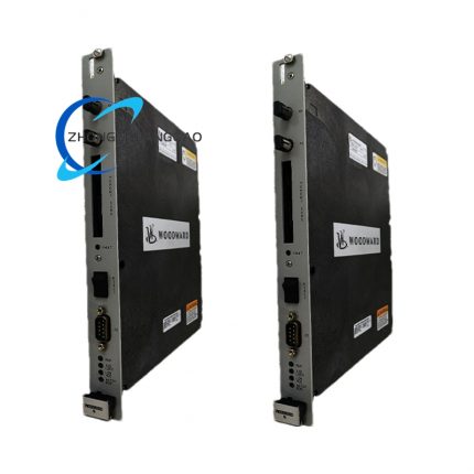
Product Brief Introduction
- Woodward 5437-523 is factory-calibrated dedicated analog field terminal module independently developed by Woodward Inc., exclusively matched with 5466-316 HD Combo I/O master control module under MicroNet Simplex control architecture, unavailable for MicroNet TMR triple redundant control system matching.
- The core function is physical wiring transfer and preliminary signal conditioning between field-site analog sensors, proportional actuators and upper-layer main control I/O card, realizing isolation filtering, signal routing for 4–20mA standard industrial analog loop signals.
- This product belongs to Woodward classic 5400 series field terminal product lineup; original manufacturer discontinued batch production after new-generation HD Combo terminal upgrade, existing inventory is original factory surplus spare unit with complete factory inspection certification file.
- Every finished unit undergoes full-channel continuity test, insulation withstand voltage test and signal precision verification before factory outbound delivery, all test data bound with single-unit serial number for full lifecycle traceability.
3. Technical Specification
- Rated working power supply: DC 24V, allowable input voltage fluctuation range: DC 21.6V ~ DC 26.4V
- Analog input channel configuration: 8-channel 4–20mA DC analog input (AI) for field pressure, temperature, displacement transmitters connection
- Analog output channel configuration: 4-channel 4–20mA DC analog output (AO), among 2 channels dedicated for proportional actuator driving control
- Backplane connection interface: Standard 37-pin male D-SUB connector for direct plugging with 5466-316 master I/O module front-end socket
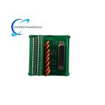
- Field wiring terminal: Green standard screw-clamp spring terminal block, each terminal supports single-core wire gauge range 0.5mm² ~ 2.5mm²
- Overall outer dimension: 158.75mm (Length) × 88.9mm (Width) × 69.85mm (Height)
- Net weight of single module: 0.281kg
- Protection grade after cabinet installation: IP20 per IEC60529 standard
- Operating ambient temperature range: -20℃ ~ +70℃; storage extreme temperature: -40℃ ~ +85℃
- Relative humidity working condition: 5%RH ~ 90%RH non-condensing environment, no corrosive gas deposition allowed
- Channel isolation specification: Independent galvanic isolation between each AI/AO channel and module power ground, isolation withstand voltage: AC 500V/1min no breakdown
4. Functional Features
- Built-in passive RC low-pass filter circuit on every signal channel, fixed cutoff frequency 50Hz, eliminating industrial field power-frequency electromagnetic interference on 4–20mA analog loop.
- Onboard field configurable solder jumpers, users adjust jumper position to switch loop power supply mode between passive field-powered and module internal powered for analog input channels.
- Screw-type wiring terminals own anti-loose spring preloading structure, preventing wire loose disconnection caused by cabinet vibration in long-term running status.
- Standard DIN35 rail buckle structure at module bottom, supporting two fixed installation modes: DIN rail mounting and flat panel screw fixing without extra conversion accessory.
- Internal overcurrent protection PTC thermistor embedded per output channel, automatic circuit cut-off once AO output loop short-circuit occurs to avoid master control module back-end circuit burnout.
- Integrated transient voltage suppression diode on each signal pin, absorbing lightning surge and instantaneous peak pulse voltage from field long-distance wiring cable.
- Channel layout follows fixed grouping design: front terminal block partitions AI area and AO area by physical spacing to avoid wiring cross interference during field construction.
- Dedicated marking label area reserved on module surface for manual marking of field device tag number and loop number to facilitate post-maintenance troubleshooting management.
5. Performance Parameter
- Full-scale signal conversion precision: ±0.1%FS under rated 24VDC power supply and 25℃ standard ambient condition
- Input channel loop impedance: ≤250Ω for all 8 AI channels under 4–20mA input status
- Output channel maximum load resistance: 600Ω for each 4–20mA AO channel at full 20mA output current
- Channel-to-channel crosstalk attenuation value: ≥60dB within 0~100Hz signal frequency band
- Continuous working long-term drift: ≤0.05%FS per 24-hour uninterrupted operation under constant-temperature environment
- Vibration resistance index: withstand 3g RMS vibration within 10~500Hz frequency range per IEC60068-2-6 standard during operation
- Single-channel response delay time: ≤8ms from field signal change to data transmitted to upper 5466-316 I/O module
- Insulation resistance between channel and ground: ≥1000MΩ tested with DC500V megohmmeter at normal ambient condition
6. Material Composition
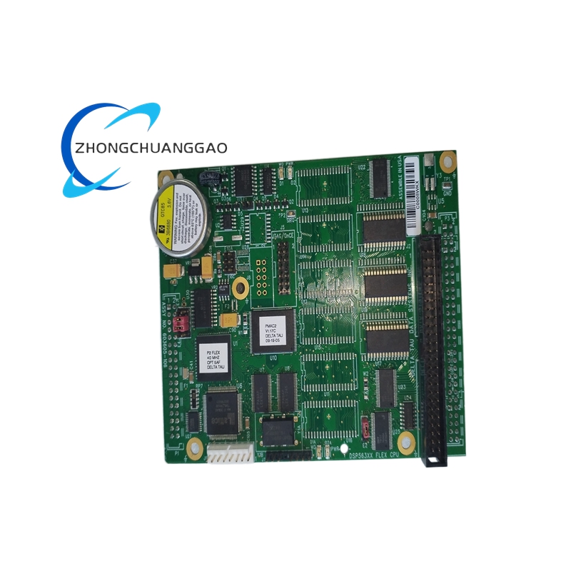
PCB Core Circuit Board
- Substrate material: FR-4 flame retardant epoxy glass fiber board with TG130 high-temperature resistance grade; surface adopts full tin-lead-free HASL anti-oxidation coating, copper foil thickness 35μm.
External Plastic Housing & Terminal Base
- DIN rail buckle and terminal insulating base: Reinforced PA66 nylon material added with glass fiber filler, flame retardant grade UL94-V0, anti-aging and anti-hydrolysis property for long-term cabinet storage.
Internal Electronic Components
- Filter capacitance: High-temperature multilayer ceramic capacitor and polypropylene film capacitor; isolation optocoupler: industrial-grade wide-temperature optoelectronic isolator with built-in dielectric isolation layer.
- Screw terminal conductive inserts: H62 brass raw material with nickel plating anti-corrosion surface treatment; fixing fasteners: SUS304 stainless steel miniature screws.
- Transient suppression components: Zinc oxide varistor and TVS diode packaged in plastic sealed form; PTC overcurrent protection component: organic polymer resettable fuse.
D-SUB Backplane Connector
- Connector shell: Zinc alloy die-casting with black electrophoretic coating; contact pin: phosphor bronze with gold-plated surface to prevent oxidation contact resistance rise.
7. Structural Characteristics
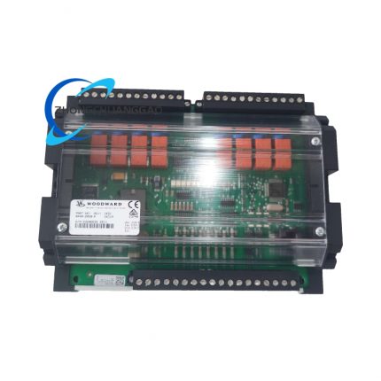
- Overall split three-part compact structure: backplane 37Pin D-SUB connector section, intermediate PCB circuit core section, front-side green screw terminal wiring section, all three parts locked by four stainless steel positioning screws into integrated unit.
- Bottom integrated one-piece DIN35 standard rail clamping buckle with built-in spring lock sheet; push-type release structure to realize quick disassembly from DIN rail without tool auxiliary.
- Terminal block arranges in single horizontal row layout, each terminal position corresponds to silk-screen printed channel number on PCB surface for direct channel identification during wiring operation.
- Module side wall reserved rectangular opening for internal jumper adjustment, matched with removable small plastic dust plug to block unused opening and prevent cabinet dust falling into inner circuit.
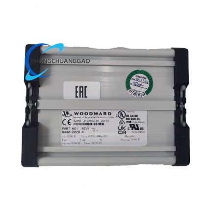
- Front-side right corner fixed white warning label with factory specified electrostatic sensitive device mark and module part number barcode for unit traceability management.
- Internal PCB fixed with insulating plastic support pillars, maintaining fixed clearance between circuit board and outer plastic shell to avoid accidental short circuit caused by metal foreign body falling.
8. Working Principle
- Field analog signals (4–20mA) transmitted from site sensors or transmitters enter corresponding AI screw terminals of 5437-523 module via shielded signal cable.
- Input signal firstly passes onboard RC passive low-pass filter circuit to filter out high-frequency clutter interference, afterward goes through galvanic isolation optocoupler to complete electrical isolation between field loop and control cabinet internal circuit, cutting common-mode ground loop interference path.
- Processed analog signal is transmitted via internal PCB wiring to rear-end 37Pin D-SUB connector, then directly uploaded to matched 5466-316 HD Combo master I/O module for analog-to-digital conversion and digital data collection.
- Digital control command sent down from MicroNet host controller passes through 5466-316 module to 5437-523’s internal drive circuit, converted into standard 4–20mA analog current signal at AO channel after signal conditioning processing.
- Generated 4–20mA output current drives field proportional actuator through AO screw terminal wiring; actuator feeds back actual position signal via separate AI channel back to control system to form closed-loop regulation control loop.
- Onboard PTC protection element automatically cut off corresponding channel circuit once AO output wire short-circuit happens, stopping overcurrent inflow and protecting front-end master control I/O module hardware from damage.
9. Advantage Highlights
- Exclusive matching design for Woodward 5466-316 I/O module achieves zero compatibility error during plug-in assembly, eliminating signal mismatch risk caused by non-original terminal adapter modification.
- Independent channel galvanic isolation design thoroughly isolates field-side ground potential fluctuation and cabinet control ground interference, improving control system anti-interference ability under complex industrial electromagnetic environment.
- Integrated filter circuit saves external independent signal isolator and filter accessory procurement cost, simplifying cabinet internal wiring layout and reducing fault points of peripheral components.
- Standard DIN rail installation mode shortens on-site wiring and module replacement construction period; damaged single module can be directly pulled out and replaced without modifying field-side wiring cable.
- Full industrial wide-temperature component selection enables stable continuous operation from -20℃ to +70℃ without extra cabinet cooling fan configuration in conventional power plant control cabinet.
- Original factory single-unit serial number traceability system supports spare part inventory management and after-sale maintenance component matching, all original spare parts keep consistent factory technical standard with discontinued production batch.
- Fixed 8AI+4AO channel layout conforms to conventional single actuator + multi-measurement point turbine/engine control loop configuration, matching most MicroNet Simplex unit standard design scheme.
10. Applicable Industries
- Thermal & Gas Power Generation Industry: Steam turbine, gas turbine, diesel generator unit control cabinet field analog signal wiring and transfer, turbine speed/valve position closed-loop control signal matching.
- Oil & Gas Upstream & Downstream Industry: Offshore oil platform compressor control system, natural gas pipeline pressure/flow transmitter signal collection and regulating valve actuator driving output.
- Marine Propulsion Industry: Vessel main engine MicroNet control system cabin-side sensor and fuel actuator signal terminal conversion, compliant with DNV-GL marine equipment certification application scenario.
- Petrochemical Refining Industry: Furnace combustion control loop, process pressure/temperature online monitoring analog signal centralized terminal processing in refining workshop DCS subsidiary cabinet.
- Industrial Compressor Manufacturing Industry: Large reciprocating and centrifugal compressor unit governor system field analog loop wiring adapter for Woodward MicroNet control platform.
- Hydropower Equipment Industry: Hydro-turbine governor control cabinet water level, guide vane opening analog signal collection and servo actuator output driving terminal application.
11. Model Series Classification
- Base standard model: 5437-523 (Simplex standard analog terminal, factory default configuration without optional accessory)
- Derivative variant 1: 5437-523-P (Pre-installed external terminal surge protection module for outdoor cabinet and high-lightning-strike industrial site usage)
- Derivative variant 2: 5437-523-C (Coated conformal paint on PCB surface for high-humidity coastal and chemical corrosive gas environment customized model)
- Derivative variant 3: 5437-523-K (Complete set with factory pre-terminated 37Pin connecting cable between module and 5466-316 I/O card as assembled kit)
12. Installation Requirements
- Cabinet environment precondition: Install inside IP54 or above sealed electrical control cabinet; installation position avoids cabinet top heat dissipation area and adjacent high-power contactor, transformer strong magnetic field component layout area.
- DIN rail installation specification: Fix standard DIN35 aluminum mounting rail horizontally inside cabinet with fixing spacing ≤150mm; clamp 5437-523 module bottom buckle onto DIN rail until audible locking click sound appears.
- Backplane connection requirement: Align 37Pin D-SUB connector with 5466-316 I/O module front socket vertically, insert horizontally without forced lateral prying to prevent connector pin bending deformation.
- Field wiring construction rule: Use shielded twisted-pair cable for all 4–20mA signal wiring; cable shielding layer single-end grounding at cabinet ground bar, field-side shielding end suspended without grounding connection.
- Power supply access standard: DC24V working power fetched from cabinet isolated regulated power supply module, power source grounding terminal connected to cabinet PE protective ground bar with wire gauge ≥1.5mm² copper wire.
- Pre-power-on inspection item: After wiring completion, use multimeter to test no short-circuit between each channel terminal and ground, confirm all wiring terminal screws tightened with specified torque 0.8N·m before switching on cabinet power.
- Post-installation commissioning: Power on whole control system and maintain 30min preheating period, calibrate full AI/AO channel signal precision with standard 4–20mA signal calibrator to finish formal commissioning acceptance.
13. Usage Precautions
- Electrostatic protection regulation: Wear certified anti-static wristband connected to cabinet ground bar when touching internal PCB circuit or adjusting onboard jumpers; prohibit direct bare-hand contact with PCB copper foil and component pins to avoid electrostatic breakdown internal chip.
- Wiring operation specification: Cut off cabinet DC24V total power supply before any field terminal wiring modification; prohibit live plugging/unplugging 37Pin D-SUB backplane connector during system running state.
- Environmental daily maintenance: Keep cabinet internal dehumidification equipment running in high-humidity working site; regularly clear cabinet accumulated dust every six months with dry compressed air (0.3MPa air pressure max) to avoid dust bridging short-circuit between terminals.
- Overload operation restriction: Strictly follow rated 600Ω maximum load resistance for AO output channel; prohibit short-circuit test on AO terminals under powered state without protection equipment access.
- Spare module storage rule: Store idle spare modules in original factory anti-static shielding bag under 15℃~25℃ dry constant-temperature warehouse environment, avoid long-term exposure to open air with corrosive gas and high dust concentration.
- Fault disposal criterion: Replace module immediately once continuous channel signal drift and abnormal heat generation happen during operation; prohibit unauthorized disassembly of module plastic shell and modification of internal original circuit component layout.
- Long-term idle equipment management: If control cabinet stops running over 60 consecutive days, cut off DC24V power supply for all 5437-523 modules; seal cabinet door tightly and place desiccant bag inside cabinet to prevent terminal corrosion caused by damp condensation.

")
")


-430x430.jpg)
-430x430.jpg)
-430x430.jpg)
Reviews
There are no reviews yet.