2. Product Brief Introduction
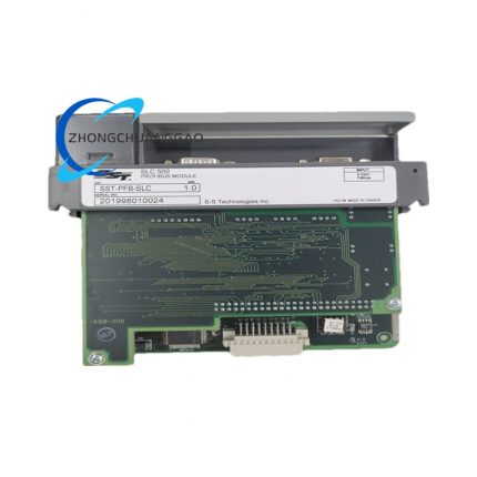
This product is a dedicated industrial-grade protocol conversion interface card designed for standard IEEE1014 VME bus architecture control systems. It establishes bidirectional real-time data transmission channel between VME bus host CPU and global standard Profibus industrial fieldbus network. The onboard independent Intel i960 RISC processor completes full Profibus protocol stack operation locally without occupying VME host computing resources, supporting synchronous multi-mode operation of Profibus-DP Master, Profibus-DP Slave and Layer2 FDL message transmission simultaneously. It realizes cyclic I/O data exchange, acyclic parameter configuration and transparent layer-two bus data forwarding between VME-based PLC/DCS controllers and field Profibus peripheral slave equipment, fully complying with DIN19245 international Profibus formal specification standards.
3. Technical Specifications
- VME Bus Standard Compliance: IEEE 1014 VMEbus, SD16 data bus width, SADO24 addressing specification, P1 connector compatible standard 6U VME slot definition
- Profibus Physical Layer: RS485 differential bus interface, standard DB9 female Profibus terminal connector
- Profibus Supported Baud Rate: Fixed full-range standard rate: 9.6kBd,19.2kBd,93.75kBd,187.5kBd,500kBd,750kBd,1.5MBd,3MBd,6MBd,12MBd
- Onboard Core Processor: Intel i960 32-bit RISC embedded CPU
- Onboard Memory Configuration:
- Local working RAM: 512KB dedicated processor RAM
- Host shared RAM: 256KB dual-mode shared memory
- Program storage Flash: 512KB sector-structured non-volatile Flash ROM
- VME Address Allocation Mode:
- Linear Mode: Occupies continuous 256KB VME address space on even 256KB boundary
- Paged Mode: Occupies fixed 16KB base space, 16×16KB page switching access for full shared memory
- Short I/O Register Space: Fixed 1KB VME short I/O address block configured via onboard 10-position DIP switch
- Power Input Rating: Standard VME slot power supply: +5VDC, rated input current 1.5A maximum full-load consumption
- Profibus Network Capacity: Single card DP Master mode supports maximum 126 field Profibus slave nodes on one bus segment
- Interrupt Definition: Supports VME IRQ1~IRQ7 configurable interrupt channel via DIP switch setting
4. Functional Features
- Three independent concurrent working modes: Profibus-DP Master cyclic I/O polling, Profibus-DP Slave passive bus access, FDL Layer2 transparent raw message send/receive; all modes run synchronously without mutual resource occupation.
- Built-in complete Profibus DP/FMS/FDL full protocol stack solidified in onboard Flash, no external host protocol driver load for basic bus operation.
- Two independent firmware loading channels: serial CONFIG debug port offline firmware download and VME host shared memory online program loading, two sets of firmware can be stored in Flash for switchable startup.
- Automatic CRC check and parity error detection for all Profibus bus data frames; abnormal frame automatically discarded with fault flag uploaded to VME host register.
- Full configurable Profibus station address via onboard rotary coding switch, address range 1~123 complying with Profibus standard station coding rule.
- Onboard multi-status LED indicator set: Power LED, Profibus bus active LED, VME bus communication LED, fault alarm LED for real-time working state visualization.
- Built-in hardware bus surge suppression circuit for RS485 Profibus port to resist industrial field surge voltage and electromagnetic spike damage.
- Compatible with standard GSD device description file; supporting all certified Profibus slave equipment parameter configuration via official SST Profibus Configurator PC software.
- Independent watchdog hardware circuit for onboard CPU; automatic hardware reset triggered upon processor program runaway to recover card normal operation.
5. Performance Parameters
- DP Cyclic Data Refresh Latency: ≤150μs minimum single slave I/O data update delay under 12MBd highest baud rate
- Maximum Profibus Cable Distance: 1200m@9.6kBd, 100m@12MBd using standard shielded Profibus twisted-pair cable
- Shared Memory Data Transfer Speed: Peak VME bus access speed reaches 160MB/s between host and card shared RAM
- Operating Ambient Temperature Range: -20°C ~ +70°C continuous rated working temperature; -40°C~+85°C sealed storage temperature
- Allowable Ambient Humidity: 5%~95% non-condensing relative humidity under full working condition
- EMC Compliance Standard: Pass CISPR22 Class B industrial electromagnetic compatibility certification, meets EN61000-6-2 industrial anti-interference specification
- Flash Data Retention Lifespan: ≥20 years non-volatile configuration data storage without external power supply
- Continuous MTBF Index: 180000 hours rated mean time between failures under standard industrial ambient environment
6. Material Composition
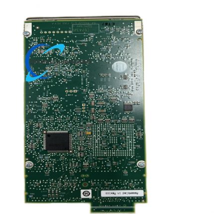
- Main Printed Circuit Board: FR-4 high Tg fire-resistant glass fiber substrate PCB with full immersion tin anti-oxidation surface coating, through-hole+SMT mixed production process.
- Card Edge Gold Finger: High-purity copper base plus 1.2μm hard gold electroplating layer for VME P1 connector plugging wear resistance.
- Connector Components:
- VME P1 backplane connector: Phosphor bronze nickel-plated terminal with PA66 UL94-V0 flame retardant plastic housing
- Profibus DB9 connector: Brass gold-plated contact with PBT insulating shell
- CONFIG serial debug port: Standard 9-pin industrial D-SUB connector
- Core Semiconductor Components: Military industrial grade Intel i960 CPU, SMD industrial DRAM/Flash memory chip, automotive-grade transient suppression diode, metal film precision fixed resistors, multilayer high-reliability ceramic capacitors.
- DIP Switch & Rotary Switch: Gold alloy contact metal switch with high-temperature resistant nylon insulation base.
- Card Front Panel Bracket: Cold-rolled steel surface zinc passivation metal panel for rack fixation and mechanical shock resistance.
7. Structural Characteristics
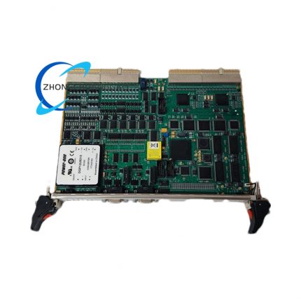
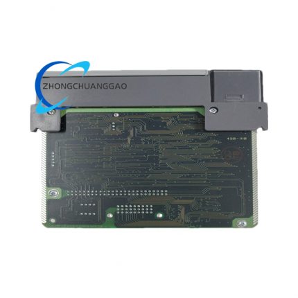
- Standard 6U VME full-size card dimension specification: Height 233.35mm, Width 160mm, overall board thickness 1.6mm matching global universal VME rack mounting size.
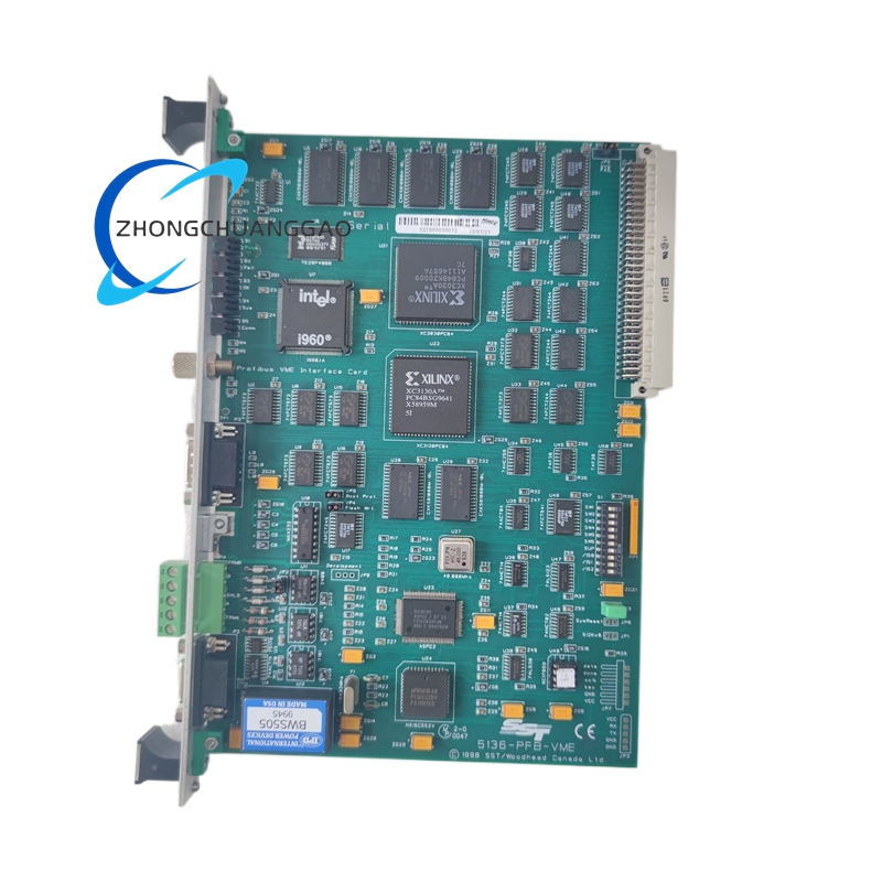
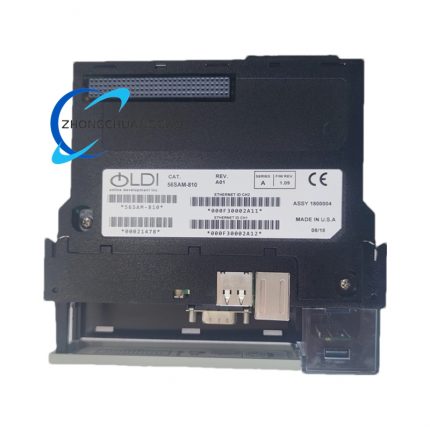
- Split front panel + main PCB integrated structure; front panel centrally arranges DB9 Profibus port, CONFIG serial port and full set status indicator LEDs.
- Onboard component partition layout: CPU & memory area concentrated at PCB central zone, VME bus gold finger on left edge, Profibus interface and switch components concentrated at front panel side for convenient field wiring and parameter setting.
- Pre-reserved multiple copper via heat dissipation layout around high-power core chips for passive natural heat dissipation without built-in cooling fan.
- Four positioning copper pillars fix core large-size SMD components to PCB substrate to avoid component displacement caused by equipment mechanical vibration.
- Onboard 10-position DIP address switch and Profibus station address rotary switch arranged on front panel inner side for easy parameter modification without card disassembly from rack.
8. Working Principle
Phase 1: VME Host Data Interaction
VME host CPU reads/writes card shared memory space via VME backplane bus according to preset linear/paged addressing mode; all upper-layer control commands and field output data are stored into shared RAM area, with hardware interrupt triggered to notify onboard i960 processor upon valid data update.
Phase 2: Onboard Protocol Processing
Intel i960 CPU extracts VME host command and I/O data from shared RAM, executes built-in Profibus protocol stack program stored in Flash memory; converts host parallel bus data into standard Profibus serial frame format complying with DIN19245 specification, then outputs to RS485 Profibus physical layer circuit.
Phase3: Profibus Bus Physical Transmission
RS485 differential driver circuit converts protocol data frames into differential electrical signals for transmission on field Profibus shielded bus cable; completes token passing scheduling for DP Master mode to poll all connected slave equipment sequentially at configured baud rate.
Phase4: Field Data Feedback & Upload
Profibus slave uploaded status and input data pass through RS485 receiving circuit and frame verification; after CRC validity check, effective field data is parsed by onboard CPU and written into specified shared RAM address area; VME host accesses updated real-time field data via VME bus periodically or via hardware interrupt trigger.
Phase5: Fault Diagnosis Processing
Real-time bus short/open circuit, baud rate mismatch and communication timeout signals captured by physical layer monitoring circuit; fault codes are written into fixed VME register address and front panel corresponding fault LED activated for local onsite indication.
9. Advantage Highlights
- Independent onboard processor offloads full Profibus protocol computing load from VME host CPU, effectively reducing main control system resource consumption and improving whole equipment operation stability.
- Triple-mode synchronous operation capability eliminates need for multiple separate interface cards when system requires mixed Master/Slave/FDL bus application, cutting cabinet slot occupation and engineering procurement cost.
- Dual firmware storage design supports emergency backup startup via offline serial port download, avoiding whole card failure caused by single firmware damage.
- Wide industrial temperature working range and reinforced anti-interference hardware design adapt high vibration, large temperature fluctuation and electromagnetic intensive harsh on-site industrial environment.
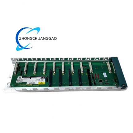
- Standard universal VME 6U form factor realizes seamless plug-and-play with all IEEE1014 compliant VME backplane racks and mainstream VME-based PLC/DCS including GE Fanuc Series 90-70 control system.
- Complete official configuration software and standard GSD file compatibility guarantee universal access to all mainstream brand Profibus field devices globally.
- Non-volatile Flash memory permanently saves configuration parameters, all bus configuration data remains intact after complete module power cut without repeated parameter setup after power restoration.
10. Applicable Industries
- Heavy Process Industry: Petrochemical refining plant, natural gas processing station, thermal power plant DCS control system interconnection transformation
- Discrete Manufacturing Industry: Automotive automated assembly production line, electronics intelligent workshop Profibus networking control, heavy machinery processing equipment centralized monitoring
- Energy & New Energy Industry: Wind farm unit control cabinet, photovoltaic centralized inverter VME control system fieldbus expansion
- Transportation Industry: Urban subway vehicle control cabinet, railway locomotive auxiliary control unit fieldbus signal conversion
- Water Treatment Industry: Large-scale municipal sewage plant DCS system, industrial circulating water automatic control equipment
- Metallurgy Industry: Steel rolling mill production line VME control cabinet Profibus network access, non-ferrous metal smelting automation system
11. Model Series Affiliation
- Parent Product Series: SST 5136 Profibus VME/PCI/ISA Multi-form Factor Communication Card Series
- Same series sibling product models:
- 5136-PFB-PCI: PCI bus Profibus interface card for industrial PC
- 5136-PFB-ISA: ISA bus legacy industrial computer Profibus communication card
- 5136-DNP-VME: VME bus DNP3 fieldbus protocol conversion card
- Matching host control equipment: GE Fanuc 90-70 VME PLC series, VME-based custom industrial embedded controller, third-party VME architecture DCS mainframe
12. Installation Requirements
- Rack Installation Environment: Install inside closed industrial control cabinet with dustproof and ventilation structure; prohibit installation in high-humidity, corrosive gas concentrated or explosive hazardous ambient space.
- Slot Mounting Rule: Insert card into free standard 6U VME slot of compliant IEEE1014 backplane; fasten front panel upper and lower fixing screws with cabinet rack to eliminate mechanical vibration gap.
- Pre-installation Parameter Setup: Complete 10-position DIP switch configuration for VME base address, interrupt channel and access permission before rack insertion; set Profibus station address via front panel rotary switch per project design requirement.
- Wiring Specification: Profibus bus wiring uses double-shielded twisted-pair Profibus dedicated cable; DB9 connector pin assignment strictly follows Profibus standard definition, install 220Ω terminal matching resistor at two physical ends of entire Profibus bus segment.
- Cabinet Space Requirement: Minimum 15mm vertical clearance reserved above and below card body inside rack for natural convection heat dissipation, no heat-generating power components closely attached to card surface.
- Grounding Specification: Connect cable shielding layer single-point to control cabinet dedicated PE protective earth terminal; separate grounding route from high-voltage power distribution cabinet ground loop to avoid common-mode interference.
- Firmware Download Rule: Complete initial firmware download via front CONFIG serial port before formal system commissioning if card is factory-new or Flash data erased.
13. Use & Maintenance Precautions
- Strictly prohibit hot plugging/unplugging card from powered VME backplane; live plug action causes instantaneous surge voltage to damage onboard CPU and memory chip permanently.
- Never connect non-RS485 standard voltage signal into Profibus DB9 port; overvoltage input directly destroys internal differential transceiver circuit.
- All address switch and rotary parameter adjustment operations must be executed after cutting off VME rack total power supply to prevent abnormal bus address conflict triggering whole Profibus network breakdown.
- Regular quarterly maintenance only uses dry lint-free cloth to wipe front panel and PCB surface dust; no organic solvent, alcohol or water cleaning liquid contact with board electronic components.
- Store spare unused cards in sealed anti-static shielding bag under 10°C~35°C dry constant temperature environment; prohibit long-term open-air storage in damp or high-temperature warehouse space.
- When replacing damaged unit on site, only original SST factory certified 5136-PFB-VME genuine replacement card is permitted; third-party refurbished or compatible imitation modules cannot access formal industrial certified control system.
- Avoid external strong electromagnetic radiation equipment (high-power inverter, high-frequency welding equipment) installed within 30cm range of control cabinet housing where card is mounted to prevent abnormal bus communication drop-out.



























Reviews
There are no reviews yet.