Technical Specifications:
- Number of Channels: 8 channels (standard) or 16 channels (extended configuration)
- Output Signal: 4–20 mA DC (2-wire loop powered)
- Output Resolution: 16-bit (65,536 steps) — 0.015% of span per step
- Output Accuracy: ±0.1% of span (typical); ±0.2% of span (maximum over temperature)
- Load Resistance: 0 to 600 Ω (at 24V DC supply)
- Compliance Voltage: 24V DC minimum (module requires external loop power supply)
- Update Rate: 1 update per controller scan cycle (50–500 ms)
- Isolation: 250 VDC channel-to-channel; 500 VDC channel-to-backplane
- Output Failure Mode: Configurable — fail high (20 mA), fail low (4 mA), or fail last value (hold)
- Operating Temperature: 0°C to 60°C (32°F to 140°F)
- MTBF: Greater than 200,000 hours
Functional Features:
- 16-bit DAC per channel — provides extremely fine control resolution
- Per-channel output fault detection:
- Open circuit detection (output current below 3.5 mA)
- Short circuit detection (output current above 21 mA)
- Wire break detection
- Fail-safe output configuration — user-selectable fail state on module fault or communication loss
- Programmable output range: 4–20 mA, 0–20 mA, or 0–24 mA (user configurable)
- Programmable damping/rate limiting — configurable output ramp rate from 0.1 to 100% per second
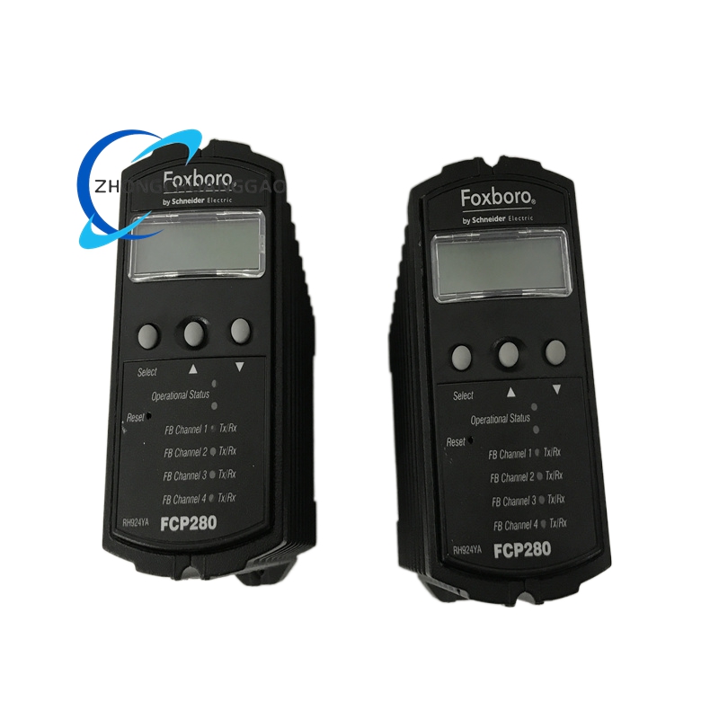
- Front Panel LEDs: Per-channel OK/FAULT indicators; module-level POWER and COMM LEDs
Performance Parameters:
- Output Linearity: ±0.05% of span
- Temperature Drift: ±0.01% of span per °C
- Channel-to-Channel Crosstalk: Less than -80 dB
- Power Consumption: 1.5W per channel (typical at 20 mA output)
- Total Module Power: Approximately 12W (8-channel) or 24W (16-channel)
- Settling Time: Less than 10 ms to within 0.1% of final value
Material Composition:
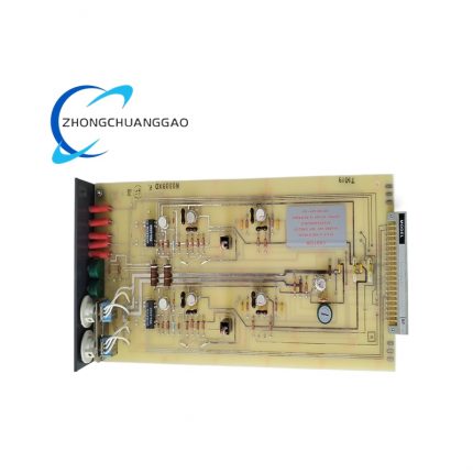
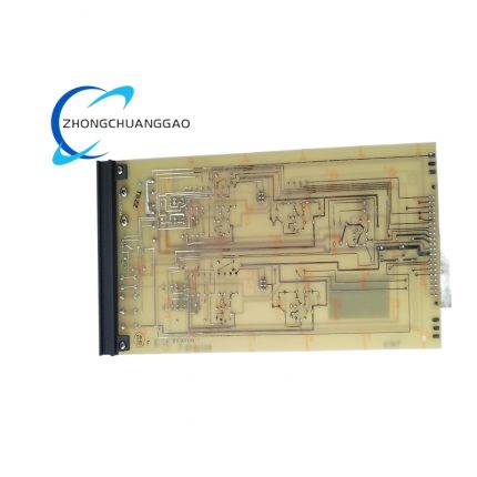
- PCB: 4-layer FR-4 with separate analog ground plane
- DAC: 16-bit multiplying DAC with laser-trimmed resistors for accuracy
- Output Driver: Precision current source with compliance voltage up to 30V DC
- Isolation: Per-channel opto-isolator with 500 VDC rating
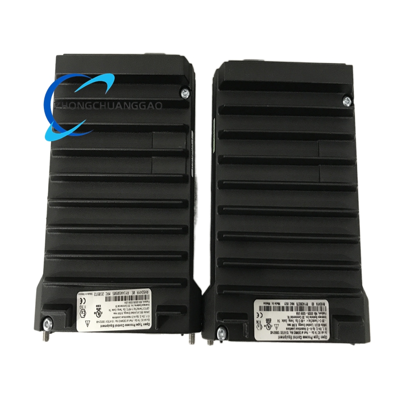
- Enclosure: Steel with zinc-nickel plating
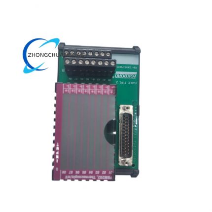
- Connectors: Screw-terminal blocks (8 or 16 channels, 2 wires per channel)
Structural Characteristics:
- Form Factor: Standard Eurocard module (160 mm × 233 mm)
- Mounting: Horizontal rack mount in I/A Series chassis
- Field Wiring: Screw-terminal connectors on front panel — wire gauge 12–22 AWG
- Weight: Approximately 0.65 kg (1.43 lbs) (8-channel version)
Working Principle:
The FBM219 processor calculates the desired output value (0–100% or engineering units) and sends a 16-bit digital value to the FCP280 via the backplane during each scan cycle. The on-board 16-bit DAC converts this value to a proportional voltage, which drives a precision current source circuit. The current source forces the configured current (4–20 mA) through the external 2-wire loop, regardless of load resistance (up to 600 Ω). Per-channel opto-isolators provide galvanic isolation between the DCS backplane and each output channel. The module continuously monitors output current and compares it to the commanded value — if a fault (open, short, or deviation) is detected, the channel is flagged and the fail-safe state is applied.
Advantages & Highlights:
- 16-bit resolution — finest resolution available in I/A Series analog output modules
- Per-channel isolation — one channel fault does not affect other channels
- Fail-safe configuration — critical for valve and actuator control safety
- Open/short circuit detection — eliminates need for external loop monitors
- Programmable damping — prevents valve hunting and actuator wear
Applicable Industries:
- Oil and Gas (control valve positioning, VFD speed control)
- Chemical (reagent feed control, pH control valve)
- Power Generation (boiler feedwater valve, damper control)
- Pharmaceutical (precise dosing control)
- Pulp and Paper (refiner plate control, basis weight control)
Installation Requirements:
- Install in any available chassis slot
- Provide external 24V DC loop power supply — module is 2-wire loop powered, does not supply loop power
- Use shielded twisted-pair cable — maximum length 1,000 meters (3,280 feet) at 24AWG
- Do not exceed 600 Ω total loop resistance — includes wire resistance + device input resistance
- Configure fail-safe state before startup — verify with control valve/actuator vendor
Usage Precautions:
- This is a 2-wire module — it does NOT power the loop; external 24V DC supply is required
- Maximum loop resistance: 600 Ω — exceeding this causes output saturation below 20 mA
- Do not apply external voltage to output terminals — will damage the current source circuitry
- Verify fail-safe state matches safety requirements — incorrect fail-safe can cause process upset or hazard




























Reviews
There are no reviews yet.