3. Technical Specifications
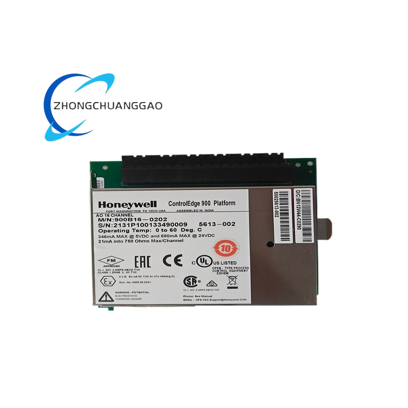
- Official Part Number: 5466-1158
- Rated Input Power Supply: 24 VDC, allowable voltage fluctuation range 21.6 VDC ~ 26.4 VDC (±10% tolerance); rated total power consumption 9.5 W
- Discrete Input Channel Configuration: Total 48-channel galvanically isolated passive DC discrete input, rated trigger voltage 24 VDC; input cut-off threshold ≤5 VDC, input effective pull-in threshold ≥18 VDC
- Discrete Output Configurable Modes: Dual optional output layouts, Mode1: 16-channel Form C isolated relay output, Mode2: 32-channel isolated transistor output; single Form C relay contact rated load: 8 A / 28 VDC resistive load
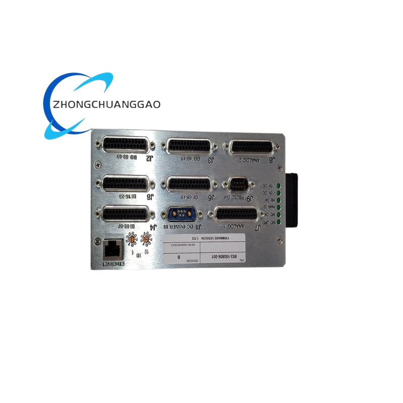
- Backplane Communication Interface: Dedicated MicroNet Plus internal rack backplane bus for high-speed cyclic data exchange with CPU5200 main controller; onboard auxiliary debug bus compatible with AppManager upper monitoring software for real-time channel data reading
- Galvanic Isolation Parameter: 500 VDC isolation between each signal channel and earth ground; 1000 VDC isolation between field signal circuit and internal main control common circuit, noise rejection ratio reaches 85 dB minimum
- Operating Ambient Temperature: -40 ℃ ~ +70 ℃; long-term storage temperature: -45 ℃ ~ +85 ℃
- Applicable Ambient Humidity: 5% ~ 95% non-condensing relative humidity for cabinet indoor installation environment
- Overall Physical Dimension: 220 mm (Height) × 128 mm (Width) × 36 mm (Thickness); net single unit weight: 610 g
- Mounting Specification: Standard MicroNet system rack card insertion installation, matches factory dedicated control rack card slot specification
- Enclosure Protection Grade: IP20 indoor cabinet exclusive use, forbids direct outdoor exposed installation
4. Functional Characteristics
- Collect passive dry-contact switching signals from field safety switches, thermal protection contacts, oil pressure auxiliary switches and generator breaker auxiliary contacts via 48 full-isolated input channels, built-in independent RC low-pass filter per channel to eliminate field power-frequency clutter and transient spike false trigger.
- Supports two switchable output deployment schemes of 16CH relay or 32CH transistor output, converts logic commands issued by upper CPU5200 controller into on-off drive signals to control on-site solenoid valves, cabinet indicator lights and small auxiliary contactors directly.
- Embedded hardware fault locking circuit, automatically locks corresponding output channel into safety off-state once single-channel output overload or short-circuit happens to prevent cascade damage to adjacent internal circuit components.
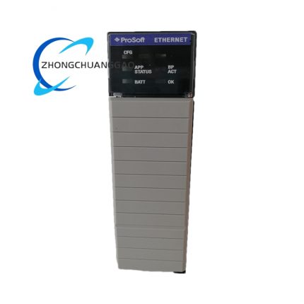
- Front panel sets independent LED status indicator for every input and output channel; input LED lights upon receiving valid 24VDC trigger signal, output LED synchronizes with actual output pull-in action state of relay or transistor circuit.
- Transmits all input status feedback and output execution state data to MicroNet main controller via backplane bus with fixed 2 ms cyclic refresh cycle for upper control system interlock logic operation and fault alarm judgment.
- No onboard adjustable potentiometer design, zero field calibration requirement after module replacement, same part number spare module can complete direct hot swap replacement without parameter reset operation.
- Realizes remote online channel diagnosis via Coder configuration software and AppManager monitoring software, supports single-channel forced output test during pre-commissioning wiring verification stage.
5. Performance Parameters
- Single input channel signal response delay: ≤2.2 ms from valid voltage access to internal register data latch completion
- Relay output mechanical pull-in delay: ≤7 ms from receiving bus command to contact stable closing
- Vibration Resistance Standard: Pass 10 Hz~150 Hz continuous random vibration test with 5g acceleration, no channel loose contact or internal component failure during full-load operation
- Impact Resistance Standard: 30g peak acceleration under powered running condition, 50g peak acceleration under transportation storage condition without internal circuit open circuit damage
- Rated full-load continuous operation MTBF: ≥310000 hours under standard rated temperature and humidity operating environment
- Channel crosstalk index: Zero effective data error generated by mutual electromagnetic interference between adjacent input/output channels under full 48DI+32DO full-load running state
- EMC Compliance Standard: Conform to IEC61000-6-2 industrial electromagnetic immunity specification and IEC61000-6-3 electromagnetic emission control standard
- Overvoltage endurance: Each input terminal continuously withstands maximum 38 VDC transient overvoltage without internal isolation circuit burnout damage
6. Material Composition
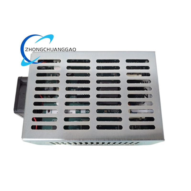
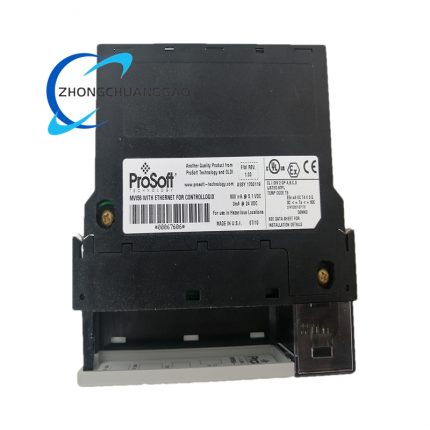
- Outer Module Metal Shell: Cold-rolled steel plate with black anti-corrosion electrostatic spraying surface treatment, anti-rust and anti-oxidation property for long-term cabinet service
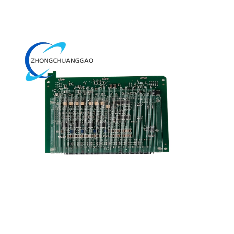
- Core Main PCB Substrate: High-Tg FR4 epoxy glass fiber flame retardant copper-clad board, all circuit bonding pads adopt immersion gold surface treatment with gold plating thickness ≥0.03 μm
- Channel Isolation Components: High-reliability optocoupler and high-voltage ceramic isolation capacitor to realize specified 500VDC/1000VDC graded isolation design
- Internal Form C Relay Core: Silver alloy contact sealed electromagnetic relay, coil adopts high-temperature resistant enameled copper wire winding, epoxy sealed housing anti-dust and anti-humidity
- Backplane Gold-plated Connector Terminal: Phosphor bronze alloy base material with nickel pre-plating plus surface hard gold plating ≥0.5 μm thickness for long-term plugging anti-oxidation
- Internal Fixed Fasteners: SUS304 stainless steel miniature anti-rust positioning screws and insulating PET plastic separation gaskets
- Front Indicator Window Component: High-transmittance anti-scratch PC transparent plastic injection molding part with anti-ultraviolet modification treatment
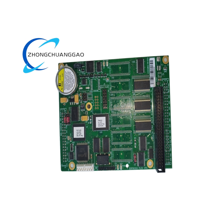
7. Structural Features
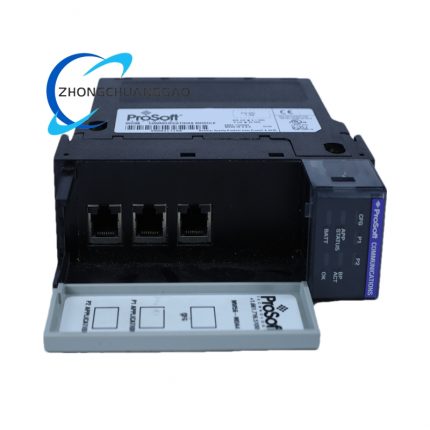
- Integral split three-section structure consisting of front indicator panel, middle main control PCB circuit board and rear backplane golden finger connector assembly, all components locked as one whole unit via perimeter positioning screws.
- Front panel zoning layout: Upper area arranges 48 input channel corresponding LED indicators, lower area reserves output channel LED indicator area matching dual 16CH/32CH configurable output modes, module model and certification marking printed at front right fixed position.
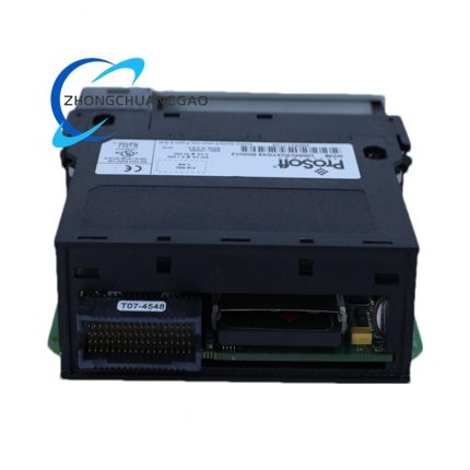
- Internal PCB physical partition layout: Independent separated regions for input signal filtering zone, output drive power zone, backplane bus logic control zone, realizing physical isolation between strong-current output loop and weak-current input signal loop to reduce cross interference.
- Rear side integrated standard MicroNet rack golden finger card structure, fixed card thickness matches dedicated control rack card slot dimensional tolerance, built-in elastic positioning shrapnel for tight slot locking after insertion.
- Internal closed insulating plastic baffles set between input optocoupler bank and output relay bank to block internal high-frequency electromagnetic radiation mutual coupling interference.
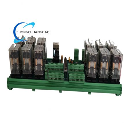
- Reserved external extension cable interface for docking two sets of 24/12 DIN-mounted discrete FTM terminal modules via dedicated high-density shielding cable to expand field wiring layout space.
8. Working Principle
After the module is inserted into MicroNet Plus control rack slot and receives rated 24VDC working power supply, onboard core logic chip completes power-on initialization and default parameter loading from internal nonvolatile flash memory. The internal polling circuit sequentially scans all 48 input channels; when field switch closes and inputs valid 24VDC voltage signal, corresponding channel isolation optocoupler is conducted to convert field alternating electrical signal into standard internal digital level and store signal status into module shared register area. Upper CPU5200 main controller cyclically reads all input register data via rack backplane bus for system interlock and protection logic calculation. When main controller sends output switch instruction through backplane bus, internal drive circuit amplifies control level to drive corresponding relay coil or output transistor to complete contact on-off action, realizing conduction control of external field load equipment connected on output terminals. Actual output contact status is synchronously fed back to main controller via backplane bus to build closed-loop output monitoring; Coder configuration software reads internal register data via auxiliary debug bus to finish parameter modification and channel online diagnosis operation.
9. Advantage Highlights
- Original Woodward factory standardized MicroNet Plus dedicated module with complete batch production traceability, zero adapter conversion required for seamless matching with CPU5200 series main controller, compatible with official Coder V5.03+ full version configuration software.
- High-density integrated 48DI configurable output design reduces total cabinet module quantity, effectively saves control cabinet internal layout space and lowers spare part stocking management cost.
- Full independent channel galvanic isolation design completely isolates field-side surge voltage and clutter interference from core main control unit, avoiding main board damage caused by field wiring short-circuit fault and improving whole control system operation stability.
- Dual optional output configuration of 16CH relay /32CH transistor realizes flexible on-site wiring adjustment adapting to different load specification demands without replacing hardware module body.
- Potentiometer-free circuit design cancels regular periodic calibration work, same part spare module realizes direct field replacement to shorten equipment maintenance downtime period.
- Full MIL-STD-202H and global UL/CE certification system supports complete equipment export delivery for overseas power generation and energy industry projects without extra certification supplement work.
10. Applicable Industries
- Thermal Power & Cogeneration Industry: Steam turbine and auxiliary genset safety interlock signal acquisition and auxiliary actuator control
- Oil & Gas Upstream Exploitation Industry: Oilfield gas compressor station, wellhead gas turbine control cabinet discrete signal collection
- Petrochemical Refining Industry: Refinery high-pressure process compressor, reformer gas turbine safety protection control system
- Distributed New Energy Industry: Biogas generator, landfill gas genset parallel cabinet switching signal monitoring
- Marine Power Equipment Industry: Vessel main diesel generator and ship auxiliary turbine monitoring control cabinet signal expansion
- Industrial Large Compressor Station Industry: Screw/reciprocating air compressor safety interlock and auxiliary equipment automatic control
11. Applicable Model Series
- Matching Main Controller Series: Woodward MicroNet Plus CPU5200 full specification main control unit, compatible with all Simplex architecture MicroNet control racks
- Peer Product Series: Woodward 5466-1157,5466-1159,5466-315 different specification MicroNet series I/O modules with different channel layout configurations
- Supporting Auxiliary Parts: Matching 24/12 DIN-mounted discrete FTM terminal modules, dedicated high-density shielding extension cables and MicroNet standard installation racks
12. Installation Requirements
- Complete module plugging operation under full power-off state of MicroNet control rack and matched CPU5200 main controller, vertically insert module golden finger into target rack card slot and push in until front panel is tightly attached with rack panel without gap.
- Reserve minimum 35 mm upper and lower natural ventilation gap around module inside cabinet, forbid full closed sealed installation without air circulation to avoid overheating damage under continuous full-load operation.
- Complete all field input/output wiring after module fixed installation, connect field 24VDC signal cable and load cable into corresponding external FTM terminal strictly following polarity definition, terminal fastening torque controlled at 0.55 N·m standard value.
- Select standard shielded twisted-pair cable for all field signal wiring, separate signal cable from high-voltage power cable with minimum 10 cm wiring spacing to reduce power frequency electromagnetic interference.
- Finish channel point-by-point input trigger test and output forced action test via Coder configuration software before overall system power-on startup, confirm all channel data feedback matches actual field equipment state.
- Confirm rack redundant 24VDC power supply wiring meets specification, dual redundant power supply wiring is recommended for critical protection interlock system application scenarios.
13. Usage Precautions
- Strictly prohibit hot plugging/unplugging module from powered MicroNet control rack slot; instantaneous surge current generated during live plugging will permanently damage internal golden finger connector and core control chip.
- Prevent conductive metal dust, engine lubricating oil, corrosive chemical liquid splashing onto module front panel and wiring terminal area; cut off rack power supply immediately once liquid permeation occurs, send module to professional maintenance after full constant-temperature drying treatment.
- Do not connect external load exceeding rated single-channel output parameter onto relay/transistor output terminals; overload load causes relay contact ablation and permanent channel invalidation failure.
- Execute quarterly regular maintenance inspection: Check cabinet internal dust accumulation, terminal wiring tightness, front panel LED indicator working status, record all inspection data into equipment maintenance archive log.
- Store unused spare module inside original factory anti-static sealed packaging box under 18 ℃~25 ℃ dry indoor environment, forbid long-term storage under direct sunlight, high temperature damp or rain immersion environment.
- Complete module firmware upgrade only during equipment scheduled shutdown maintenance window, forbid online firmware updating during continuous production running state to avoid whole control system temporary communication interruption risk.

")
")


-430x430.jpg)
Reviews
There are no reviews yet.