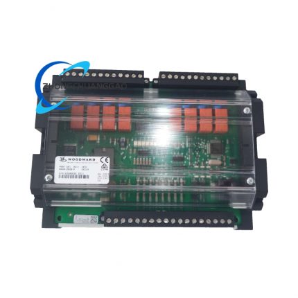
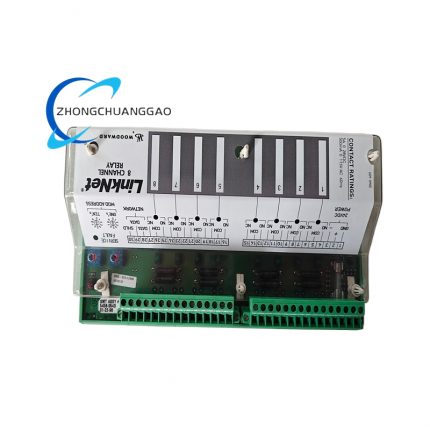
Product Brief Introduction
- This module is the exclusive matched field terminal signal processing accessory independently developed by Woodward for the classic 2301A engine/turbine speed governor controller, functioning as intermediate signal transfer carrier between on-site magnetic pickup(MPU) speed sensors, 4–20mA analog field transmitters, hydraulic actuators and main governor control board.
- It completes full signal filtering, surge suppression, circuit isolation and terminal wiring distribution for all input & output control signals of the governor system, eliminating field power grid interference and wiring confusion of on-site control cabinets.
- All finished products pass 96-hour continuous aging test, EMC electromagnetic compatibility inspection and full-channel signal calibration per Woodward original factory industrial standard before factory delivery, supporting long-term uninterrupted stable operation in high-dust, vibration, wide-temperature industrial field environment.
3. Technical Specifications (Core parameters marked in bold)
Electrical Specifications
- Rated Nominal Working Input Voltage: DC 24V, universal allowable working voltage fluctuation range: DC12V~DC36V
- Maximum quiescent operating power consumption: 12VA, peak instantaneous load current: 2A
- Analog signal input specification: Standard 4–20mA current signal, 1–5VDC voltage signal, MPU frequency pulse signal (500Hz~12000Hz switch configurable via DIP dial switch)
- Digital communication interface: Standard RS485 physical port, fixed Modbus RTU communication protocol, default factory baud rate 9600bps, 8 data bit, 1 stop bit, no parity
- Internal isolation withstand voltage: Optocoupler isolation between field signal circuit and core control circuit ≥2500VAC
- Working ambient temperature range: -40℃~+85℃ continuous rated operating range; certified storage temperature range: -55℃~+100℃
- Relative humidity standard: 5%~95% non-condensation operating humidity, no corrosive gas surrounding environment
- Protection grade: PCB inner circuit conformal coating anti-corrosion treatment; terminal area IP20 protection rating, outer assembled housing reaches IP65 dustproof and splash-proof standard
Physical Dimension Specification
- Overall outer dimension: 165mm (Width) ×125mm (Height) ×55mm (Depth)
- DIN standard rail installation occupied width: 35mm, compliant with EN50022 industrial DIN rail mounting specification
- Net single unit weight: 0.32kg, original factory packaging gross weight: 0.78kg including installation accessories and wiring terminals
Channel Configuration Specification
- Analog input channel: 8 isolated analog signal input terminals
- Frequency pulse input channel: 2 dedicated MPU speed pickup signal input terminals with built-in notch filter circuit
- Control output channel: 6 isolated drive output terminals matching hydraulic actuator control signal
- Bus communication terminal: 1 group RS485 bus positive/negative wiring terminal block
- Power supply terminal: Independent DC24V positive, negative and protective grounding dedicated terminals
4. Functional Features
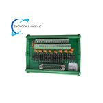
- Multi-type signal centralized wiring distribution function: Uniformly integrate speed pulse signal, analog process signal, actuator drive signal and communication bus signal into standardized screw-type terminal block, standardize on-site field wiring layout.
- Built-in multi-stage signal filtering function: Equipped with RC low-pass filter and fixed-frequency 3000Hz notch filter circuit inside, automatically eliminate power frequency clutter interference and actuator excitation harmonic noise from field input signals.
- DIP switch configurable frequency matching function: Four-position dial switch on PCB to switch four fixed MPU frequency receiving ranges (500~1500Hz /1000~3000Hz /2000~6000Hz /4000~12000Hz) to match different engine speed sensor output frequency parameters.
- Full-channel overvoltage & surge protection function: Every input and output channel is equipped with TVS transient suppression diode and ceramic discharge tube, blocking instantaneous surge voltage from field equipment reverse breakdown internal circuit components.
- Isolated signal conversion function: All field-side and control-side circuits adopt optoelectronic full isolation design, cutting off ground loop interference caused by potential difference between on-site equipment and control cabinet power supply.
- Fault passive isolation function: Single-channel short-circuit or abnormal overload only locks corresponding independent channel without affecting full-module and whole governor system normal operation.
- System expansion compatibility function: Support cascading multi-module via RS485 bus, expand multi-set engine unit centralized signal collection for parallel genset synchronization control system.
5. Performance Parameters
Signal Processing Performance Index
- Analog signal conversion precision: Full-scale sampling error ≤±0.1% under rated operating temperature
- Pulse frequency acquisition accuracy: Frequency measuring error ≤±1Hz within full 500~12000Hz rated receiving range
- Signal response delay: Single-channel signal transmission delay ≤2ms after filtering processing
- Filter clutter suppression ratio: ≥45dB for 50Hz industrial power frequency interference signal suppression
Reliability Performance Index
- Rated MTBF (Mean Time Between Failures): ≥92000 hours under specified standard industrial operating environment
- Anti-vibration performance: Comply with IEC60068-2-6 industrial vibration standard, pass 5g RMS random vibration durability test from 10Hz~150Hz frequency sweep
- Factory calibration valid period: 24 months per original factory component calibration specification
- Conformal coating service life: ≥10 years anti-humidity and anti-corrosion service life under non-corrosive rated environment
Electrical Safety Index
- Reverse power connection protection: Automatic power input cutoff protection when DC power positive and negative reversed, no internal component burnout
- Overcurrent protection: Each independent channel equipped with miniature fuse, cut off loop within 5μs when overload current exceeds rated limit
6. Material Composition
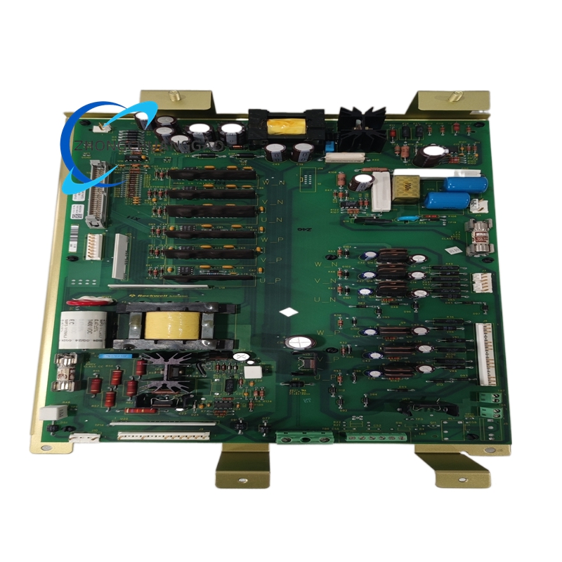
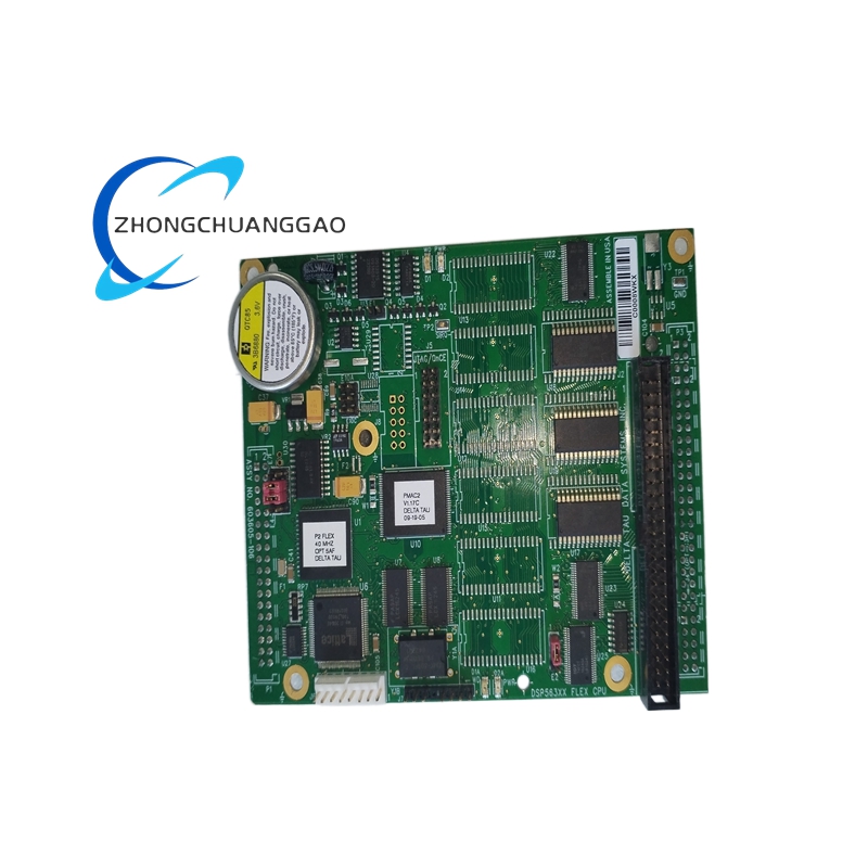
- Main Circuit Substrate: FR-4 high Tg fire-resistant double-sided copper-clad PCB board, full board surface with UL certified lead-free HASL tin plating, whole PCB coated with acrylic conformal insulating varnish.
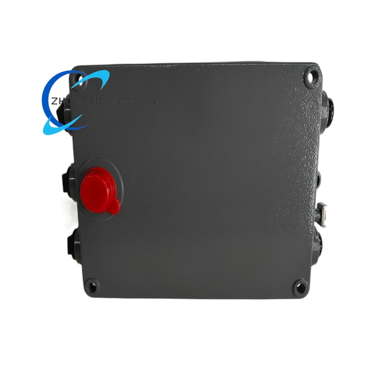
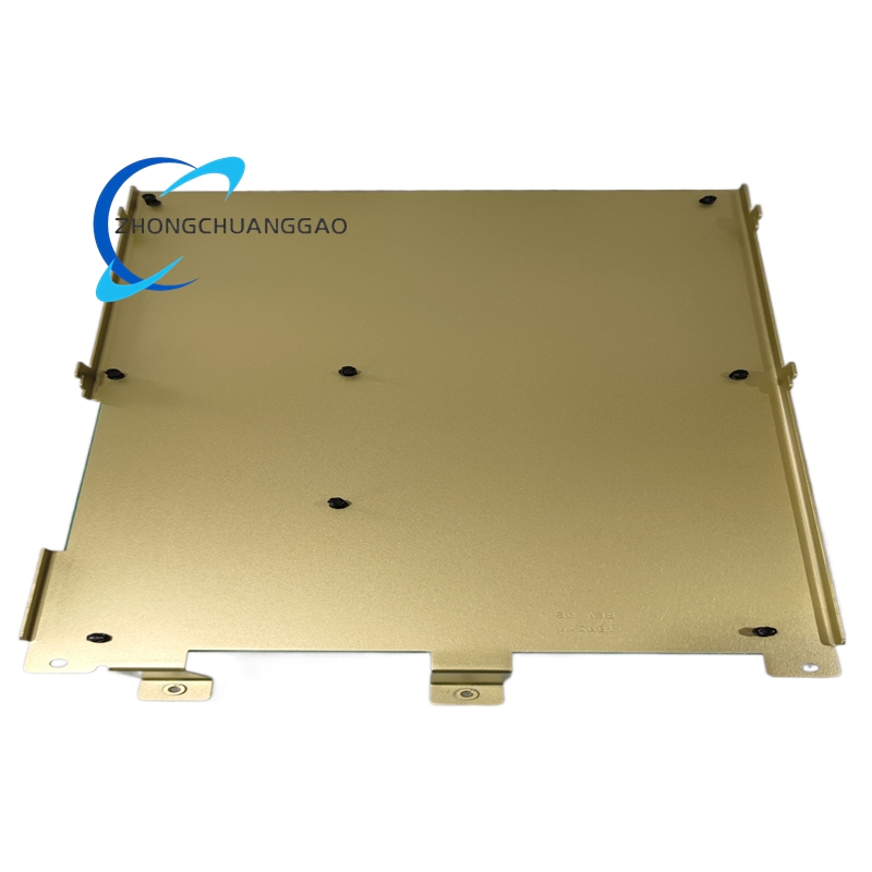
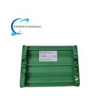
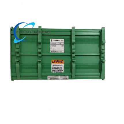
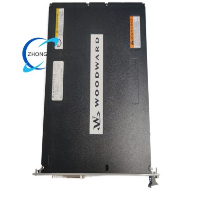
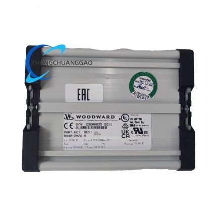
- Outer Installation Shell: Extruded aluminum alloy frame with black hard anodizing anti-oxidation surface treatment, high thermal conductivity for passive heat dissipation of internal circuit heat accumulation.
- Wiring Terminal Components: Nickel-plated brass screw-type spring terminals with PA66 UL94-V0 flame retardant plastic terminal base, anti-loose stainless steel fastening screws.
- Core Electronic Components: Industrial-grade wide-temperature SMD MCU chip, military-spec optocoupler isolation components, metal film precision fixed resistors, high-reliability tantalum electrolytic capacitors and gas discharge surge tubes.
- Dial Switch Assembly: Gold-plated contact DIP toggle switches with high-temperature resistant PBT plastic housing for long-term stable frequency range switching operation.
7. Structural Characteristics
- Overall split three-layer modular layout: Separated into outer aluminum fixed frame, middle main PCB circuit board layer and front terminal wiring layer three independent assembled structures, fixed by anti-loose stainless steel screws without structural displacement under long-term vibration.
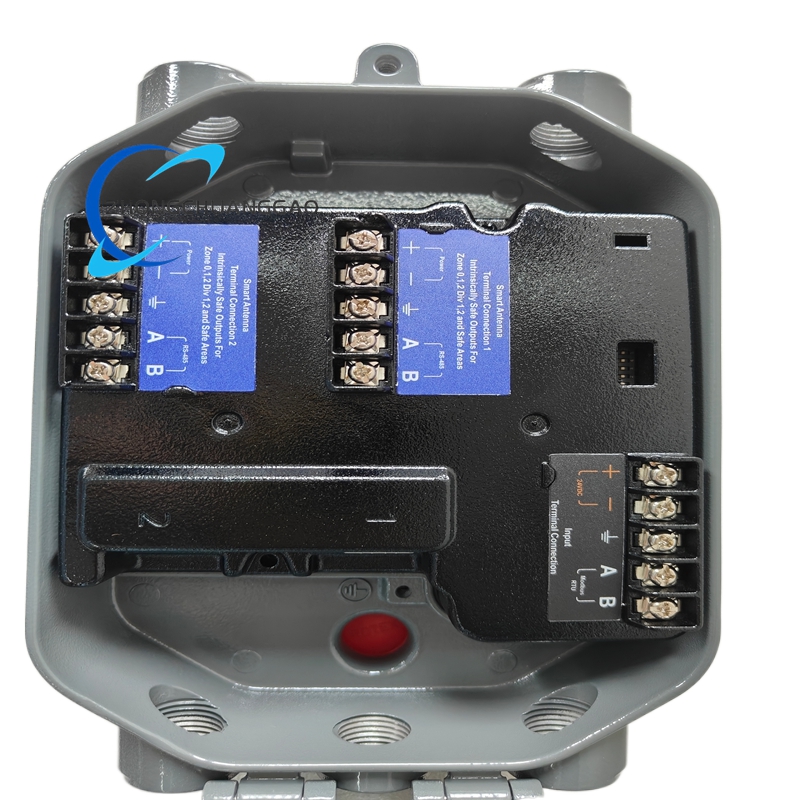
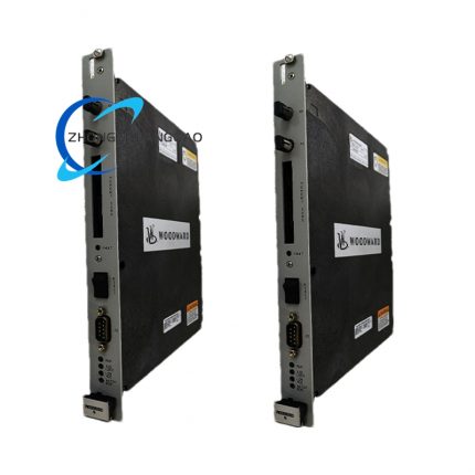
- Front panel layout: Upper area four-position DIP frequency dial switch group; middle area orderly arranged multi-group screw wiring terminal blocks divided by signal type (power/input/output/bus); lower area module specification model marking area and grounding reserved terminal.
- Internal partition structural design: Insulating plastic barrier strips separate analog signal area, frequency pulse area and power drive area on PCB to avoid crosstalk interference between different types of signals.
- Rear mounting structure: Standard DIN rail buckle clamping structure integrated on rear aluminum shell, quick snap-on fixed onto EN50022 standard DIN installation guide rail inside control cabinet without extra drilling fixation.
- Sealing structural design: Gap between shell and PCB filled with closed-cell silicone foam sealing strip to block dust and moist air entering inner circuit cavity from cabinet gap.
8. Working Principle
- Power input stage: External DC24V regulated power access dedicated power terminal block; internal EMI filter circuit converts fluctuating input voltage into multiple groups of stable isolated DC working voltage for MCU control unit, signal conditioning circuit and terminal protection circuit respectively.
- Field signal receiving stage: MPU speed pickup frequency pulse, 4–20mA analog process signal and actuator feedback signal transmit into corresponding input terminals; built-in RC filter and fixed notch filter eliminate clutter interference from original field signals; DIP switch sets effective receiving frequency range for pulse signal before signal enters isolation optocoupler unit.
- Signal isolation & conversion stage: Optocoupler components complete electrical isolation between field side and governor control side; conditioned analog and pulse signals are converted into standard digital signal format by on-board MCU and sent to matching 2301A main governor controller via internal bus line.
- Control output transfer stage: 2301A controller outputs speed adjustment drive signal according to speed closed-loop operation algorithm; the signal transmits into this module’s output terminal after secondary isolation protection, then forwards to on-site hydraulic fuel actuator to adjust fuel/steam flow for prime mover speed regulation.
- Communication & fault monitoring stage: RS485 Modbus bus terminal receives upper DCS/SCADA system remote parameter reading command; on-board real-time circuit monitoring chip continuously detect each channel voltage/current status, output abnormal fault flag signal to main controller once channel overload or short-circuit occurs.
9. Advantage Highlights
- Original factory matching design exclusively for Woodward 2301A governor series, full signal protocol and electrical parameter one-to-one matching with main controller, zero signal attenuation and compatibility failure during long-term system operation.
- Full-channel multi-layer surge+isolation+filter integrated circuit design, drastically reduce field complex industrial environment electromagnetic interference impact to governor closed-loop speed control precision.
- Four-gear frequency dial switch free configuration adapts all mainstream diesel/gas engine and turbine MPU speed sensor output frequency specifications, no extra external signal conversion module required for on-site commissioning.
- DIN standard rail compact installation design saves control cabinet internal layout space, realizes standardized and neat field wiring construction, shorten equipment installation and after-sales maintenance cycle.
- Wide-temperature grade full industrial component configuration and whole-board conformal anti-corrosion coating, reliably operate under high-dust, high-humidity, alternating cold-hot harsh site conditions such as offshore platform and mining plant.
- Unified original factory spare part interchange standard, same-series NetCon terminal modules can be mutually replaced during on-site fault maintenance without secondary program modification of governor system.
10. Applicable Industries
- Power Generation Industry: Diesel/gas generator set centralized control cabinet signal distribution, emergency backup genset speed control system matching, islanded small power station turbine governing signal processing.
- Oil & Gas Industry: Natural gas pipeline compression unit turbine governor signal collection, oilfield fracturing pump diesel engine control terminal wiring, offshore platform gas turbine control system accessory configuration.
- Marine Engineering Industry: Cargo ship main propulsion diesel engine speed control cabinet field terminal, offshore supply vessel auxiliary genset signal conditioning module.
- Petrochemical Industry: Refinery process steam turbine and recycled gas compressor governor system signal distribution, chemical plant cogeneration unit CHP prime mover control matching.
- Mining Industry: Large mining haul truck diesel engine governing control wiring terminal, underground fixed emergency power genset signal processing module.
11. Model Series Classification
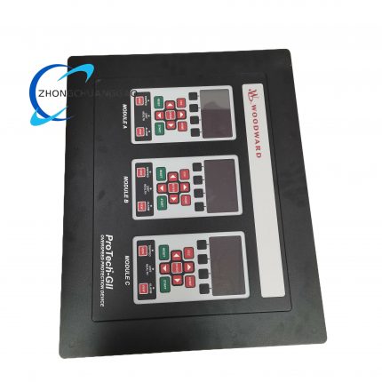
- Parent Product Platform: Woodward NetCon Field Terminal Module Series + 2301A Digital Governor Control Product Line
- Same series derivative model branches of FTM product:
- 5437-671: Basic version without built-in frequency notch filter circuit for ordinary indoor genset control
- 5437-672: Standard enhanced version with full filter and four-position frequency dial switch (target product of this document)
- 5437-673: Explosion-proof customized variant with intrinsically safe terminal design for petrochemical explosive hazardous area installation
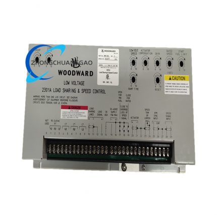
- Matching core master controller model: Woodward 2301A all-range digital speed governor controller
12. Installation Requirements
- DIN Rail Mounting Specification: Select standard 35mm width EN50022 DIN mounting rail inside control cabinet, snap module rear buckle onto DIN rail horizontally, ensure module fixed without left-right sliding under equipment long-term vibration.
- Wiring Specification: Use 0.75mm²~1.5mm² stranded copper insulated wire for signal terminals, 1.5mm²~2.5mm² copper wire for DC24V power wiring; strictly separate power wiring and signal wiring routing with spacing above 30mm to avoid electromagnetic crosstalk interference.
- Ambient Installation Environment Requirement: Install position keeps away from high-power contactors, frequency converters and compressor high-temperature exhaust air outlet; surrounding environment avoids direct water splashing, corrosive gas accumulation and strong mechanical shock source.
- Protective Grounding Standard: Connect module dedicated grounding terminal to control cabinet unified protective grounding copper bar with yellow-green 2.5mm² grounding wire, overall system grounding resistance ≤4Ω per IEC industrial electrical standard.
- Bus Wiring Specification: RS485 Modbus bus adopts daisy-chain sequential wiring layout, prohibit star-type parallel wiring mode; install matching terminal resistance at the last module tail end of whole bus loop.
13. Usage Precautions
- Power-on Preheating Regulation: Complete continuous 15 minutes power-on preheating after DC24V power input before formal system parameter commissioning, wait internal circuit temperature stabilize to guarantee signal conversion precision reach factory calibrated nominal value.
- Terminal Daily Maintenance Regulation: Tighten all terminal fastening screws once every 6 months to prevent wire loose contact caused by long-term equipment vibration; wipe module surface dust only with dry anti-static cotton cloth after cutting off upper-level total power supply.
- Prohibited Disassembly Regulation: No disassembly of sealed aluminum outer shell without Woodward official authorized maintenance technician; internal PCB components are sensitive to static electricity, dust and mechanical impact damage.
- Long-term Idle Storage Specification: When module is out of service for over 30 days, detach from DIN rail, place into original factory sealed moisture-proof packaging carton under 10℃~35℃ dry indoor storage environment, avoid low-temperature frost and high-humidity mildew corrosion of inner circuit board.
- Live Operation Prohibition: Cut off front-end DC power supply circuit breaker before any terminal wiring modification or internal component inspection; prohibit live plugging of field input/output wiring to prevent instantaneous short-circuit burnout of core MCU chip.
- Periodic Calibration Regulation: Complete full-channel signal precision recalibration every 24 months per original factory maintenance specification; replace aging terminal plastic parts and failed filter components only with Woodward certified original spare parts.

")
")


Reviews
There are no reviews yet.