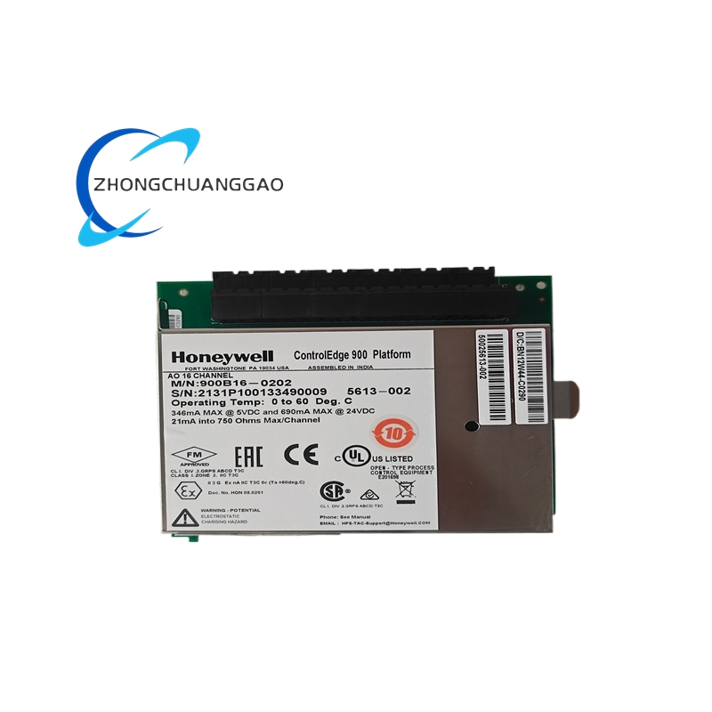
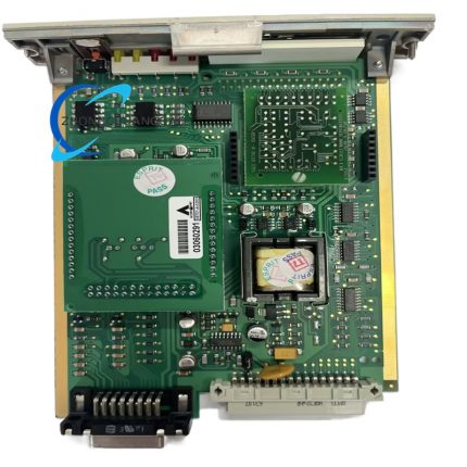
Product Brief Introduction
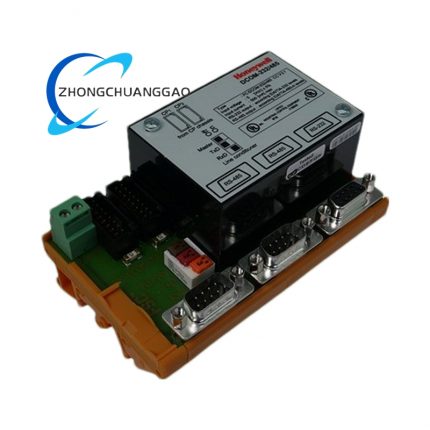
- Honeywell 05704-A-0144 is factory pre-calibrated four-channel dedicated control card exclusively developed for catalytic bead type combustible gas detectors, supporting independent constant-current power supply and signal collection for maximum four separate catalytic gas sensing probes at the same time.
- This card converts tiny resistance variation signal generated by catalytic bead combustible gas sensor into standardized voltage signal, completes internal signal amplification, bridge balance correction and gas concentration threshold comparison, then outputs relay switch alarm signal to upper monitoring cabinet and DCS system.
- Every finished product undergoes full-load continuous aging test, channel precision calibration, open/short-circuit fault simulation test and insulation withstand voltage test before factory delivery; each single card carries exclusive serialized production coding to realize full lifecycle spare part traceability management.
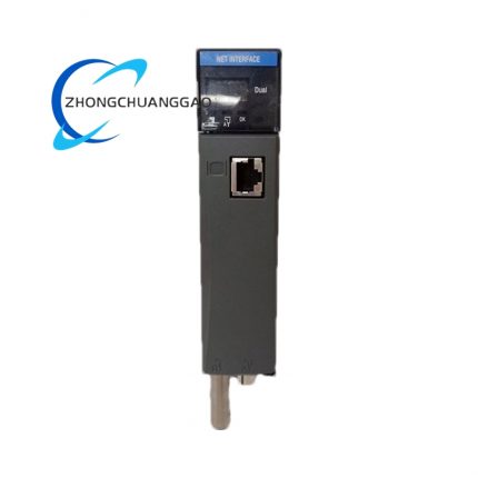
- The card is designed for fixed slot plug-in installation inside Honeywell System57 standard rack chassis, fully compliant with EN50270 industrial gas detection safety certification standard, dedicated for industrial site combustible gas leakage continuous monitoring control system configuration.
3. Technical Specification
- Rated DC working supply voltage: 24VDC, allowable input fluctuation range: 18VDC ~32VDC
- Typical static operating power consumption: 8.5W, maximum full-load power consumption under four-channel full sensor access: 12.8W
- Catalytic sensor driving current regulation range: 90mA~315mA, adjustable in fixed 1mA single-step increment mode via internal electronic setting
- Maximum single-channel output driving voltage for sensor loop: 10VDC fixed upper limit
- Effective full-scale input signal voltage range from catalytic bridge circuit: 15mV ~300mV DC
- Maximum permissible field wiring loop resistance per channel (including built-in catalytic bead sensor): 40Ω under 200mA rated driving current condition
- Bridge circuit unbalance protection fixed threshold: ±100mV offset relative to central balance point under standard 2V bridge working voltage
- Overall outer dimension: 122mm(H) ×52mm(W) ×132mm(D)
- Single bare card net weight: 0.141kg
- Protection grade after rack cabinet installation: IP20 complying with IEC60529 industrial enclosure standard
- Continuous rated working ambient temperature range: -20℃ ~ +60℃; long-term storage extreme temperature range: -40℃ ~+85℃
- Allowable working environment relative humidity: 5%RH~90%RH non-condensing, no sulfur-containing corrosive gas and dense dust accumulation environment
- Vibration resistance standard: comply with IEC60068-2-6, continuously withstand 2.2g RMS vibration within 10Hz~500Hz frequency band during normal powered operation
- Certified industry compliance standards: EN50270, UL, CE, RoHS industrial electrical certification
4. Functional Features
- Four completely independent isolated signal acquisition channels, each channel configures standalone constant-current source driving circuit to avoid mutual electrical interference between different sensor loops.
- Embedded full electronic bridge balance automatic correction circuit and signal gain adjustable circuit, no mechanical potentiometer required for on-site zero calibration of catalytic gas detector.
- Built-in three-layer fault self-diagnosis logic for each individual channel: catalytic bead open-circuit detection, sensor wiring short-circuit detection and single catalytic bead core failure identification function.
- Front panel equips four groups of independent LED indicator lamps corresponding to four channels respectively, separate green RUN status lamp and red FAULT/ALARM lamp for real-time working status visualization display.
- Onboard four groups of isolated SPDT relay contact output terminals, each channel independently drives external audible alarm, field indicator lamp and safety cut-off solenoid valve equipment without intermediate relay conversion.
- Reserved bottom edge gold-plated edge connector matching System57 rack backplane bus, realizes unified power supply and system communication bus docking after card slot insertion.
- Internal transient surge suppression circuit configured at every sensor signal input terminal, eliminates instantaneous lightning surge and power grid clutter interference transmitted via long-distance field wiring cable.
- Non-volatile onboard memory chip stores each channel’s calibrated zero point and gain parameter data; parameter data keeps complete without power supply backup after cabinet total power cut-off.
5. Performance Parameter
- Full-scale signal input detection basic precision under standard 25℃ ambient condition: ±1%FS fixed accuracy
- Long-term continuous working zero drift of single channel circuit: ≤0.08%FS per 24-hour uninterrupted powered full-load operation under constant temperature environment
- Single channel relay contact mechanical service life under rated load: ≥1,000,000 times normal switch action cycle
- Insulation resistance between internal power supply circuit and four-channel sensor input circuit: ≥1300MΩ measured with DC500V megohmmeter at normal ambient temperature
- Dielectric withstand voltage between input power terminal and card metal fixed frame: AC1800V/1min without breakdown, creepage discharge and insulation breakdown phenomenon
- Channel response delay from effective combustible gas signal input to relay contact pull-in output: ≤180ms fixed full processing period
- Anti-ambient stray electromagnetic interference capacity: maintain normal measurement accuracy under 10V/m RF electromagnetic field interference per IEC61000-4-3 standard specification
6. Material Composition
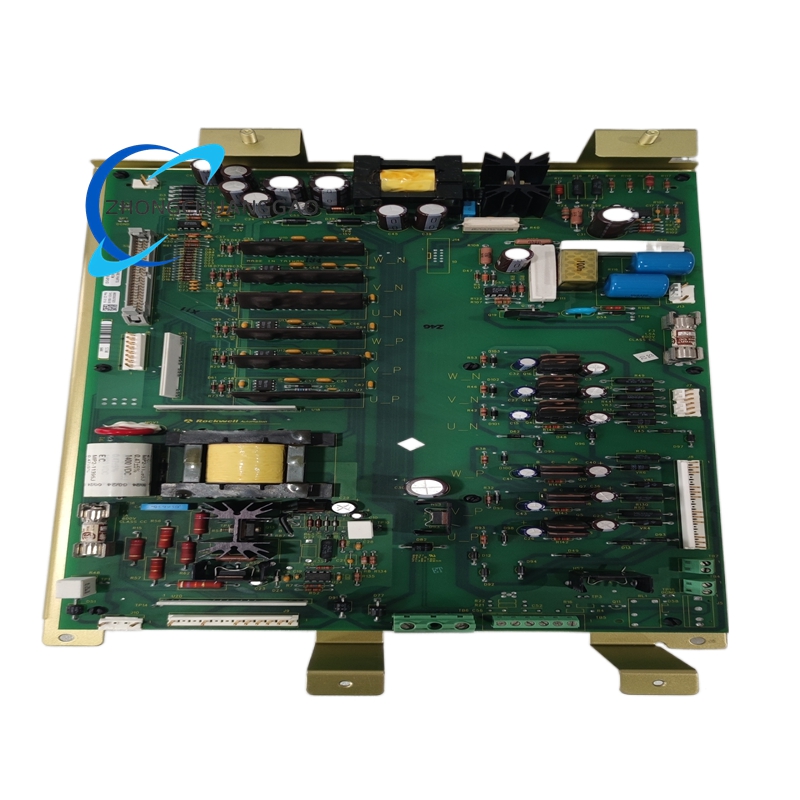
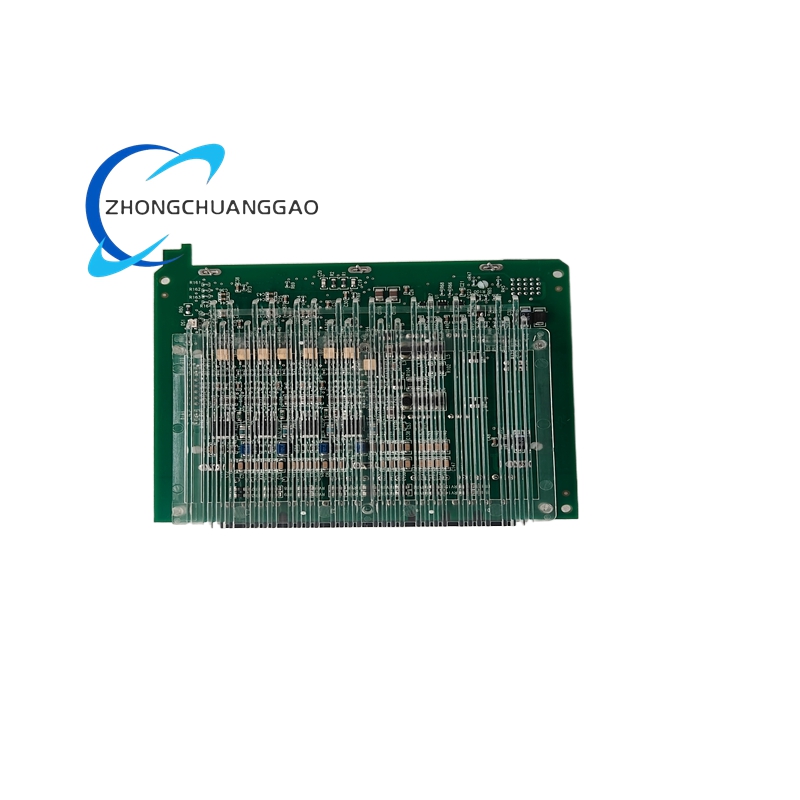
Core Main PCB Substrate
- Base plate raw material: FR-4 TG140 high-temperature flame retardant epoxy glass fiber laminated board, 4-layer PCB layout; power layer copper foil thickness 35μm, signal layer copper foil thickness 18μm, surface adopts lead-free HASL anti-oxidation coating treatment.
Edge Connector & Terminal Insulation Base
- Gold-plated edge connector plastic base: UL94-V0 grade glass fiber filled PA66 nylon injection molding; internal conductive contact pins: phosphor bronze base material with 1.0μm full gold plating anti-oxidation treatment.
Internal Core Electronic Components
- Constant-current control master IC: industrial wide-temperature grade dedicated constant-current chip; signal operational amplifier: low drift precision industrial operational amplifier; filter component combination: high-temperature aluminum electrolytic capacitor + polypropylene film fixed capacitor + multilayer ceramic chip capacitor.
- Alarm output relay: sealed miniature SPDT electromagnetic relay with silver alloy contact for anti-arcing long service lifespan; fault indicator LED: epoxy sealed anti-vibration industrial LED component.
Fixed Fastening & Auxiliary Parts
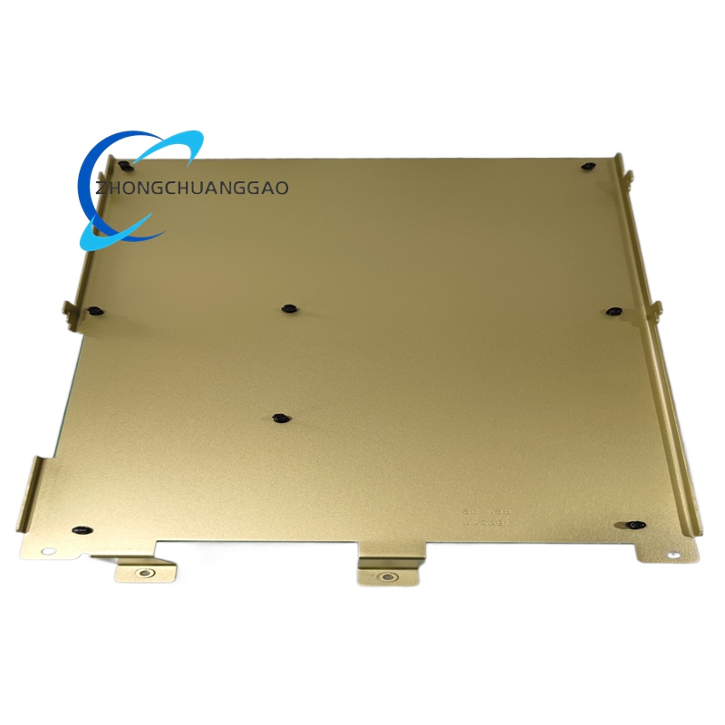
- All internal assembly locking screws and fixed hardware: SUS304 stainless steel miniature fasteners; card outer fixed positioning baffle: cold rolled SPCC steel plate with black matte electrophoretic anti-rust coating.
Optional Conformal Coating Version Raw Material
- PCB surface protection coating: transparent acrylic three-proof conformal paint for high-humidity and corrosive gas environment customized variant models.
7. Structural Characteristics
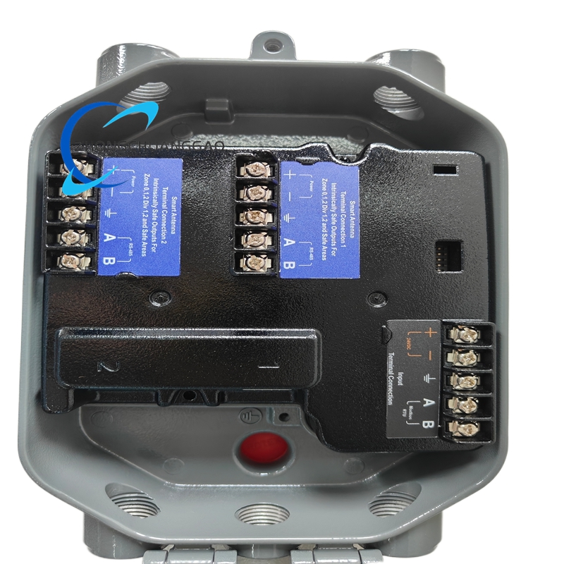
- Overall integrated single-card standard 3U rack plug-in structure, split into three functional areas: front panel indication region, middle core PCB circuit region, rear gold-plated edge connector docking region, fixed as a whole via evenly distributed stainless steel anti-loose screws.
- Front panel fixed layout: four pairs of red/green status indicator lamps arranged horizontally in equal spacing, corresponding channel number silkscreen printed directly beside each lamp group for quick channel identification during maintenance.
- Rear end adopts keyed anti-misplug edge connector design with physical positioning notch to prevent reverse insertion damage of card and rack backplane socket pins during installation.
- Card upper and lower frame reserved strip-shaped natural convection ventilation slots for internal power heating component heat dissipation, avoiding over-temperature drift of precision sampling circuit under continuous full-load running.
- Side panel blank white marking area reserved for manual writing of equipment cabinet number and corresponding field detection area number for spare part inventory and maintenance management work.
- Internal PCB fixed with high-temperature insulating plastic support pillars to maintain fixed safe creepage distance between circuit board and metal fixed frame, preventing accidental short-circuit caused by floating metal debris falling inside chassis.
8. Working Principle
- External cabinet 24VDC rated working power is transmitted via System57 rack backplane bus to card internal power conversion circuit, which outputs multiple groups of isolated stable DC working voltage for four-channel constant-current driving circuit, signal amplification circuit and relay drive circuit respectively.
- Each independent channel constant-current source outputs fixed set driving current to field catalytic bead combustible gas sensor loop; catalytic bead generates corresponding resistance variation when contacting combustible gas to form unbalanced bridge voltage signal at bridge circuit output terminal.
- Tiny bridge voltage signal is sent into multi-stage fixed-gain amplification circuit for amplitude boosting, then transmitted to internal digital comparison unit to compare real-time sampling value with pre-calibrated zero point and alarm threshold parameter stored in non-volatile memory chip.
- When sampled gas concentration value exceeds preset alarm threshold, internal drive circuit triggers corresponding channel SPDT relay pull-in action, relay contact outputs switch signal to drive external alarm horn, site warning lamp and safety interlock cut-off equipment; meanwhile corresponding channel red ALARM LED lights up steadily.
- Once field sensor wiring open-circuit, short-circuit or catalytic bead core damage occurs, channel self-diagnosis circuit immediately triggers fault output state, red FAULT indicator lamp illuminates and relay switches to fault alarm output mode synchronously.
- Built-in input surge suppression components absorb abnormal peak pulse voltage introduced by field long-distance cable lightning interference and power grid clutter, ensuring circuit measurement accuracy without false alarm or fault misjudgment.
9. Advantage Highlights
- Original matching design for Honeywell full series catalytic bead combustible gas sensors eliminates signal mismatch and calibration failure risk caused by third-party non-original replacement control card.
- Full electronic zero and gain adjustment structure cancels mechanical adjustable potentiometer, avoids precision drift caused by potentiometer aging and mechanical vibration in long-term industrial operation environment.
- Four-channel independent isolated design realizes single-channel fault shutdown without affecting normal detection operation of remaining three sensor loops, improving overall system continuous monitoring reliability.
- Complete multi-type fault automatic diagnosis function covers wiring fault and core sensor failure without additional external detection auxiliary modules, simplifying cabinet internal wiring layout and reducing peripheral fault nodes.
- Wide-temperature grade component material selection enables stable continuous operation within -20℃~+60℃ without extra cabinet forced cooling fan under standard industrial control cabinet environment.
- Standard System57 rack plug-in installation mode supports hot-swap replacement after rack power maintenance cut-off, shortens on-site fault spare part replacement construction cycle greatly.
- Front panel independent channel indicator layout enables maintenance personnel to complete rapid fault positioning between gas over-limit alarm and equipment circuit failure via lamp status observation without disassembling cabinet wiring.
10. Applicable Industries
- Petrochemical Refining Industry: Refinery production workshop, oil depot, liquefied hydrocarbon storage tank area combustible gas leakage fixed monitoring cabinet core signal acquisition configuration.
- Natural Gas Pipeline & Gas Station Industry: Urban gas transmission station, CNG/LNG filling station compressor room combustible gas detection control system card installation.
- Pharmaceutical Chemical Industry: Chemical synthesis workshop, solvent storage warehouse flammable organic vapor continuous fixed detection matching application.
- Coal Mine Processing Industry: Coal washing plant, coal chemical conversion workshop combustible coal gas leakage safety monitoring control cabinet deployment.
- Food & Beverage Manufacturing Industry: Alcohol fermentation workshop, edible solvent storage room flammable gas concentration safety monitoring system configuration.
- Waste Treatment Environmental Protection Industry: Hazardous waste storage workshop, biogas generation station combustible methane fixed gas detection control system matching.
11. Model Series Classification
- Base standard model: 05704-A-0144 (Factory default bare PCB card without pre-assembled wiring harness, standard indoor environment version)
- Derivative variant 1: 05704-A-0144-C (PCB full acrylic conformal coated three-proof customized model for coastal high-humidity and chemical corrosive gas environment)
- Derivative variant 2: 05704-A-0144-K (Complete accessory set model with factory pre-terminated four-channel sensor input wiring cable and relay output terminal plug accessories)
- Derivative variant 3: 05704-A-0144-EX (Intrinsic safety optimized version matching Ex ia IIC T6 certified field catalytic gas detectors for explosion hazardous zone installation)
12. Installation Requirements
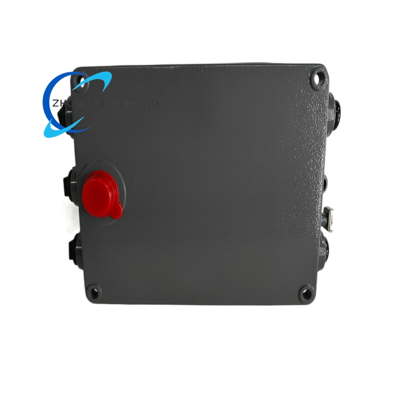
- Cabinet pre-installation environment standard: Install inside IP42 and above closed System57 standard metal rack cabinet; keep card installation slot over 110mm spacing away from cabinet internal AC contactor and high-power transformer strong magnetic field components.
- Rack plug-in installation specification: Align card rear keyed edge connector with rack backplane socket positioning notch, push card horizontally along slot guide rail until edge connector fully locks into backplane socket with fixed in-place feedback; forced reverse plugging is strictly forbidden to prevent pin bending damage.
- Field sensor wiring construction rule: All catalytic probe field wiring adopts double-core shielded twisted cable; cable shielding layer single-end fixed grounding at cabinet PE protection ground bar, field sensor terminal shielding end suspended without grounding treatment.
- DC power wiring specification: Fetch 24VDC control power from cabinet isolated safety power supply; power ground wire connected to cabinet PE copper bus bar with conductor cross-section ≥1.0mm².
- Pre-power-on inspection requirement: After all field wiring connection finished, use multimeter to confirm no short-circuit between each channel input terminal and card metal frame ground before switching on cabinet total DC power supply.
- Post-installation calibration specification: Complete cold-state no-gas power-on preheating for 30 minutes after card installation, then finish each channel zero point and alarm threshold calibration under fresh air environment before formal equipment commissioning.
- Cabinet ventilation constraint: Keep rack surrounding ventilation space unobstructed without baffle or foreign object covering card upper and lower heat dissipation ventilation slots to guarantee normal heat dissipation effect.
13. Usage Precautions
- Electrostatic protection regulation: Wear certified anti-static wristband reliably connected to cabinet PE ground bar when pulling out card or opening cabinet for internal parameter setting; bare-hand direct contact with PCB circuit board and gold-plated edge connector pins is strictly forbidden to avoid electrostatic breakdown of precision internal chip components.
- Live operation restriction: Cut off cabinet 24VDC total input power completely before any channel terminal wiring modification; live plugging/unplugging of field sensor signal cable during normal equipment running state is prohibited.
- Daily maintenance specification: Clean card surface accumulated floating dust every six months with dry compressed air at maximum 0.3MPa air pressure; avoid high-pressure air direct blowing to PCB welding spot and electrolytic capacitor component area.
- Load constraint regulation: Strictly control external relay output load not exceeding rated contact capacity; access of inductive load without intermediate contactor conversion is forbidden to prevent relay contact ablation damage.
- Spare card storage standard: Store idle spare control card inside original factory anti-static shielding carton under 15℃~25℃ dry constant-temperature warehouse environment, far away from corrosive chemical reagent and high dust concentration storage space.
- Fault disposal criterion: Cut off corresponding channel power supply immediately once abnormal shell overheating, burnt component smell or continuous irregular indicator flicker occurs during operation; unauthorized disassembly of card outer frame and modification of internal original circuit layout are prohibited, contact Honeywell official after-sales technical engineer for professional maintenance service.
- Long-term idle equipment management: If detection cabinet stops continuous operation over 60 consecutive days, cut off all 05704-A-0144 cards DC input power; place desiccant bags inside closed cabinet to prevent internal PCB damp condensation corrosion and component aging failure.

")
")
")


-430x430.jpg)
-430x430.jpg)
-430x430.jpg)

Reviews
There are no reviews yet.