Product Brief Introduction
- This unit is microprocessor core intelligent synchronization controller dedicated for single-phase & three-phase AC diesel/gas generating sets, automatically completes frequency difference, phase difference and voltage difference closed-loop matching before generator grid paralleling operation.
- The controller outputs raise/lower analog regulating signals to match external engine speed governor and generator automatic voltage regulator(AVR), sends breaker closing relay signal once all synchronization parameters reach preset qualified threshold.
- Every finished unit undergoes full function aging test, synchronization precision calibration, high-low temperature cycling verification and EMC anti-interference inspection before factory delivery, conforming to CE, UL and SIL2 international industrial safety certification standards.
- It supports standalone genset island running control, multi-unit parallel load sharing control and off-grid/grid-connected mode switch, parameter configuration realized via front panel key operation or Woodward exclusive ToolKit upper computer software through serial communication port.
3. Technical Specifications (Core parameters marked in bold)
Electrical Power Specification
- Dual optional rated input power supply: Nominal 24VDC (continuous allowable fluctuation range:18VDC~36VDC) or 120VAC (continuous allowable fluctuation range:90VAC~140VAC)
- Typical static operating power consumption:18W; maximum instantaneous peak power consumption under full relay output status:25W
- Internal power circuit isolation grade: Reinforced isolation between sampling input circuit and power main circuit, withstand voltage 2000VAC 50Hz for 60s without breakdown.
Signal Input Specification
- Generator voltage sampling input range: 0~277VAC single-phase voltage sampling, 0~480VAC three-phase line voltage sampling
- Grid bus voltage sampling input range consistent with generator sampling specification, input signal internal with lightning surge suppression circuit.
- Digital switch input channel:6 groups passive dry contact input for external run permission, breaker feedback and mode switching signal collection.
Control Output Specification
- Analog regulating output: 2-channel isolated 0~20mA DC raise/lower current signal for speed governor and AVR adjustment, single channel maximum load driving impedance ≤550Ω.
- Relay switch output:3 groups SPDT industrial grade relay, single contact rated capacity:8A/250VAC for grid switch closing command output.
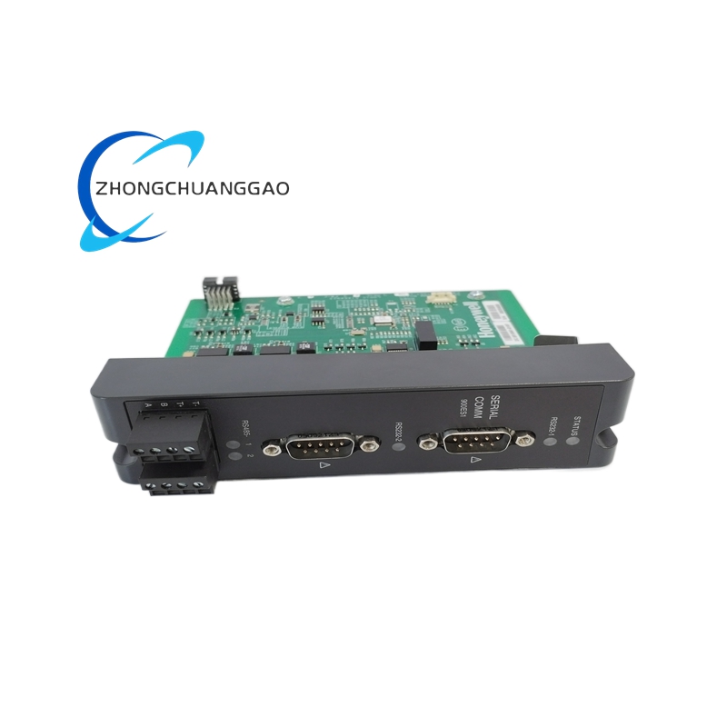
Communication Specification
- Standard built-in RS232 + RS485 dual serial communication interface, support Modbus-RTU industry standard protocol and Woodward proprietary configuration communication protocol.
- Communication maximum wiring distance: RS485 up to 1200m with shielded twisted cable; RS232 fixed maximum wiring length 15m.
Environmental & Physical Specification
- Continuous rated operating ambient temperature range: -40℃~+70℃; certified long-term component storage temperature range:-45℃~+125℃
- Working environmental humidity:5%~95% non-condensing relative humidity, condensation inside casing is strictly prohibited during continuous operation.
- Enclosure protection grade: IP30 front panel protection rating; internal circuit board conforms to IP20 protection standard.
- Overall outer dimension: 130mm(Height)×160mm(Width)×80mm(Depth); net single unit weight:420g.
- Installation specification: Standard DIN35 rail clamping mounting + cabinet panel embedded mounting two fixed modes, embedded hole reserved size:112mm×142mm.
Synchronization Core Index
- Qualified closing threshold: Phase difference ≤±2°, frequency difference ≤±0.1Hz, voltage difference ≤±3% of rated sampling voltage.
- Synchronization regulating response speed: Full adjustment cycle from out-of-tolerance to qualified synchronization ≤2.2s under rated working condition.
4. Functional Features
- Automatic three-dimensional synchronization matching function: Real-time collects generator and grid voltage, frequency, phase three core parameters, outputs continuous raise/lower regulating signal to eliminate deviation automatically.
- Multi-operation mode switching function: Built-in standalone island operation, single unit grid-connected, multi-unit parallel load sharing three configurable running modes via front panel key setting.
- Synchronization interlock protection function: Prohibits breaker closing output when voltage/frequency/phase exceeds preset safe threshold to avoid out-of-step closing damage of generator set.
- Built-in parameter memory function: All configured synchronization threshold, regulating speed and protection parameters are stored in non-volatile EEPROM chip, data remains permanently after complete power cut-off.
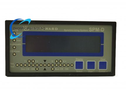
- Real-time data display function: Front panel LCD screen cycles display real-time voltage difference, frequency difference, phase angle and running state code.
- Fault self-diagnosis & code prompting function: Automatically detect sampling circuit open-circuit, power supply over/under voltage and output short-circuit fault, display corresponding fault code on screen for rapid troubleshooting.
- Adjustable regulation speed setting function: On-site configurable slow/fast two-level raise/lower regulating rate to match different response speed specifications of matched engine governor and AVR.
5. Performance Parameters
Synchronization Precision Index
- Static phase synchronization control accuracy: ≤±1° mechanical phase angle under 25℃ rated ambient environment
- Frequency steady-state control precision after paralleling: ≤±0.05Hz full range of rated frequency
- Voltage matching steady-state error after regulation completion: ≤±1.2%FS of sampling rated voltage
Reliability Lifespan Index
- Factory certified continuous service lifespan: Minimum 60000 hours stable continuous running under standard non-corrosive industrial cabinet environment
- Vibration durability compliance: Pass IEC60068-2-6 10Hz~200Hz full frequency sweep vibration test without parameter drift and component loose failure.
- Temperature cycling reliability: No functional abnormality after 1200 cycles of -40℃ ↔ +70℃ alternating temperature cyclic aging test.
Anti-interference Performance Index
- Power supply ripple tolerance: Allow input DC/AC power supply peak-to-peak ripple ≤18% rated voltage without synchronization control logic disorder.
- Electromagnetic compatibility compliance: Fully meet IEC61000-6-2 industrial EMC standard, keep stable operation under surrounding frequency converter, starter and relay switching electromagnetic interference environment.
6. Material Composition
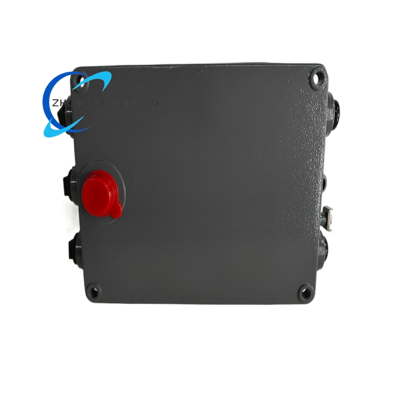
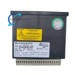
- Outer Instrument Housing: Black ABS+PC fire-retardant alloy plastic shell with UL94-V0 flame retardant certification, anti-aging matte surface coating treatment.
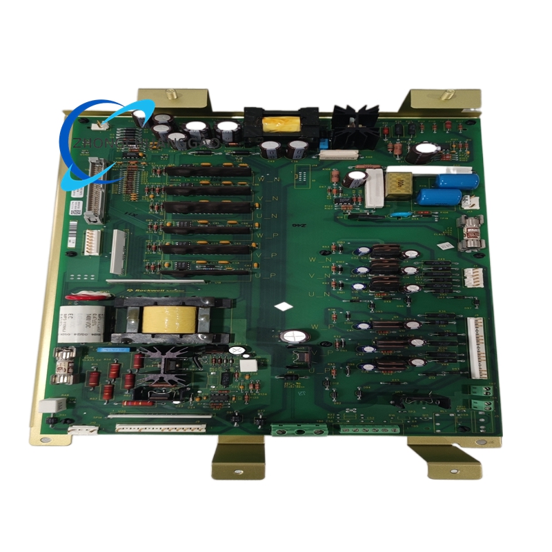
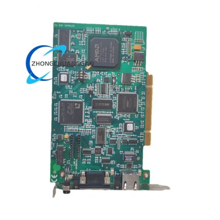
- Main Control Circuit Board: FR-4 grade flame retardant epoxy PCB board, internal copper wiring thickness 35μm, full circuit conformal coating anti-moisture paint.
- Core Control Chip: Industrial grade 32-bit single-core microprocessor with wide temperature grade working chip for synchronization algorithm operation.
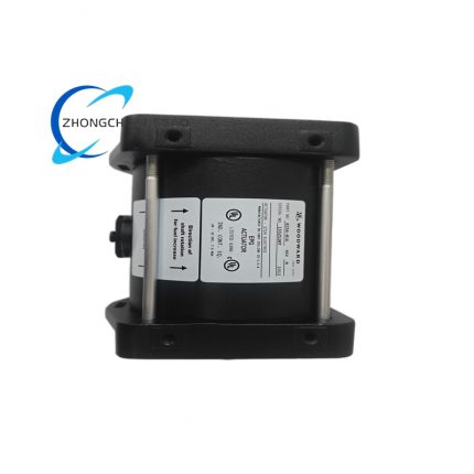
- Terminal Components: PA66 glass fiber reinforced flame retardant plastic terminal base, tin-plated phosphor bronze alloy wiring terminals for external cable connection.
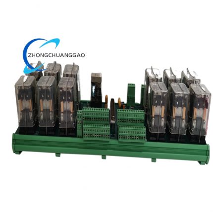
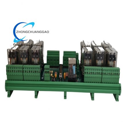
- Internal Relay Components: Silver alloy contact electromagnetic relay with high-temperature resistant plastic encapsulation for breaker control output.
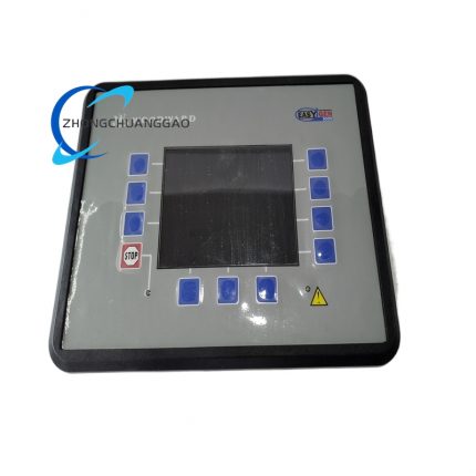
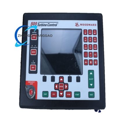
- Front Panel Display Assembly: Industrial grade negative LCD screen + silicone rubber physical operating keys with wear-resistant surface coating.
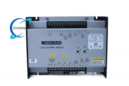
7. Structural Characteristics
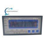
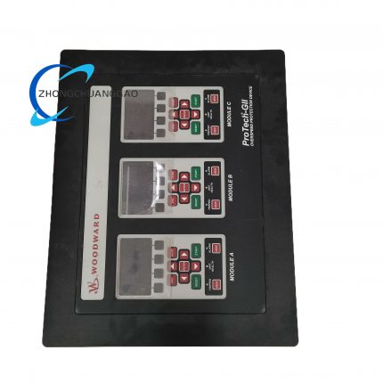
- Front panel integrated operation layout: Upper part LCD digital display area, middle running status indicator lamp area, lower four independent parameter setting function keys layout for centralized operation management.
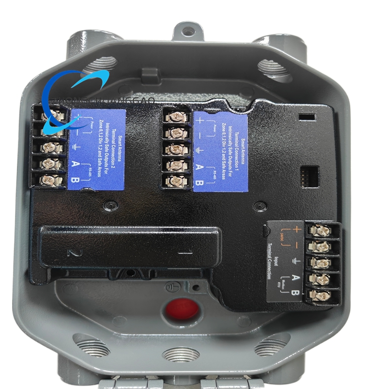
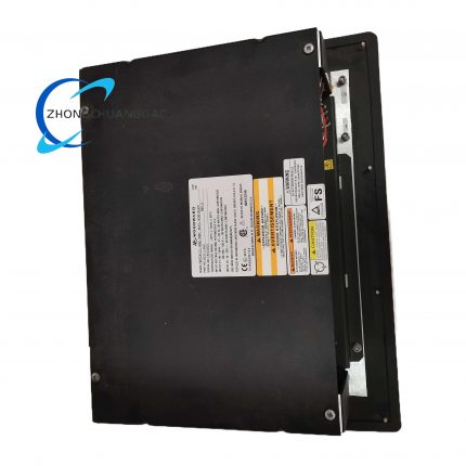
- Split front-rear cavity separation structure: Front panel display operation cavity and rear wiring terminal cavity separated by internal plastic partition board, independent sealing space for display circuit and power control circuit respectively.
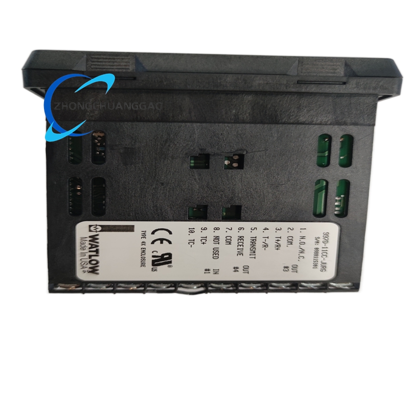
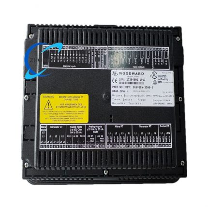
- Bottom centralized terminal layout: All sampling input, power input and control output terminals concentrated on rear bottom side of shell, partitioned labeling for different signal type wiring zoning management.
- Dual-purpose fixed installation structure: Top and bottom shell reserved DIN rail buckle structure and four fixed mounting screw holes, compatible with DIN35 standard guide rail and cabinet panel embedded installation two ways.
- Built-in passive heat dissipation structure: Multiple uniform heat dissipation slit on left and right side of plastic shell, rely on natural air convection for internal component heat dissipation without built-in cooling fan.
8. Working Principle
- Power supply conversion stage: External rated DC/AC power access internal isolated power management module, converted into multi-channel stable low-voltage DC power for main control chip, sampling circuit, display module and relay drive circuit separately.
- Signal sampling collection stage: Generator terminal voltage and grid bus voltage access isolation sampling circuit, analog voltage signal converted into digital data and transmitted to main microprocessor via high-speed AD conversion chip.
- Synchronization operation calculation stage: Internal synchronization algorithm compares collected generator and grid voltage, frequency, phase three groups of digital data, calculates deviation value and corresponding raise/lower regulating duty cycle signal.
- Regulating signal output stage: Calculated control signal is converted into 0~20mA analog current output to matched engine governor and AVR, adjusting engine speed and generator excitation voltage continuously to narrow three core parameter deviation.
- Closing instruction output stage: When all three synchronization indexes drop within preset qualified threshold, internal control logic drives closing relay action to output dry contact signal for grid breaker closing execution.
- Fault protection locking stage: When sampling circuit break, power supply overvoltage or output short-circuit abnormal state appears, internal hardware protection circuit locks all regulating and closing output immediately, meanwhile corresponding fault code is displayed on front LCD screen.
9. Advantage Highlights
- Ultra-wide dual power supply compatible design adapts to 24V battery-powered genset and 120VAC industrial control power supply two mainstream field power supply environment without extra power conversion accessory.
- High-precision multi-dimensional synchronization algorithm realizes ultra-low deviation grid connection, effectively eliminates generator closing impulse current to protect unit stator winding from impact damage.
- Dual communication interface configuration supports local key configuration and remote upper computer centralized parameter modification two operation modes, convenient for power station centralized automatic management.
- Full range hardware fault diagnosis function rapidly locates wiring fault and internal component abnormality, drastically shortens on-site equipment troubleshooting time.
- Non-volatile parameter storage design avoids repeated parameter reset after accidental power outage, improving field operation efficiency of power station equipment.
- Compact integrated cabinet mounting size saves control cabinet internal layout space compared with split type discrete synchronization components.
- Full matching compatibility with all Woodward series speed governors and mainstream domestic and foreign generator AVR products.
10. Applicable Industries
- Power Generation Industry: Distributed diesel/gas genset power station grid-connected synchronization control, multi-unit parallel load sharing management of industrial self-provided power plant, emergency standby generator automatic grid access control.
- Marine Power Industry: Inland cargo ship and ocean vessel auxiliary genset on-board power grid parallel synchronization control, ship emergency backup generator automatic paralleling system configuration.
- Petroleum & Gas Industry: Oilfield movable gas-driven generator set grid synchronization, natural gas processing plant self-contained power station multi-unit parallel control.
- Mining Industry: Underground coal mine fixed standby diesel generator automatic grid connection control, open-pit mine movable power station genset synchronization matching.
- Construction Engineering Industry: Large construction site temporary self-provided power plant multi-generator parallel running control, emergency engineering mobile power vehicle grid synchronization configuration.
11. Model Series Classification
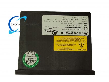
- Parent Product Line: Woodward SPM-D Full Series Generator Synchronizer Controller Family
- Same-series core derivative model classification:
- 8440-1710D: Basic single-function version only with synchronization closing function without load sharing regulation output
- 8440-1713D: Standard full-function mainstream industrial model (archived target product) with synchronization + load matching dual core functions
- 8440-1718D: Explosion-proof enhanced customized version for ATEX Zone2 hazardous gas environment power station
- Compatible matching product series: All Woodward 2301/EGP series engine speed governors, Basler, Avrtex mainstream industrial generator AVR regulators
12. Installation Requirements
- Panel Embedded Mounting Specification: Cut reserved 112mm×142mm rectangular hole on cabinet metal panel, embed controller into hole, fasten four side fixing clips with M2.5 screws, ensure front panel closely fits cabinet surface without gap.
- DIN Rail Mounting Specification: Snap bottom buckle onto standard DIN35 top-hat guide rail, push controller horizontally until full clamping fixed, single unit lateral reserved ≥25mm clearance space for heat dissipation air circulation.
- Wiring Specification: Power main circuit wire adopts ≥0.75mm² stranded copper cable; voltage sampling input wire uses shielded twisted cable with shield layer single-end grounded at cabinet ground bar; separate power wiring and sampling signal wiring with spacing ≥18mm to avoid electromagnetic crosstalk.
- Cabinet Environmental Installation Restriction: Install inside closed ventilation control cabinet, stay away from frequency converter, high-power contactor and engine starter strong electromagnetic radiation components, reserve ≥30mm free space around controller periphery.
- Pre-power-on Inspection Rule: Complete all wiring continuity and short-circuit inspection before first energization; restore all factory default parameters then reconfigure on-site matching parameters after power-on initialization.
13. Usage Precautions
- Power-on Preheating Regulation: After connecting rated working power, keep controller idle energized for minimum 3 minutes preheating before formal synchronization debugging to stabilize internal sampling circuit working precision.
- Parameter Modification Regulation: Core synchronization threshold and regulating rate parameter modification can be executed under live power status, but parameter change must be verified by one no-load synchronization test immediately after setting completion.
- Anti-liquid Infiltration Regulation: Prevent engine lubricating oil, cleaning water and corrosive chemical liquid from splashing onto rear terminal area; liquid infiltration causes terminal short-circuit and internal circuit burnout.
- Long-term Idle Storage Specification: Remove all external wiring after dismounting for idle storage over 30 days, place inside original factory sealed anti-static carton under 10℃~35℃ dry indoor environment away from corrosive volatile gas.
- Live Operation Forbidden Regulation: Strictly prohibit live plugging/unplugging of rear wiring terminal block; live wire plug operation triggers instantaneous surge voltage damage of internal AD sampling chip.
- Periodic Maintenance Regulation: Complete annual routine maintenance under full power-off state including fastening loose terminal screws, wiping front panel and terminal dust with dry compressed air; replace damaged spare parts exclusively with Woodward original certified accessories.

")
")


-430x430.jpg)
Reviews
There are no reviews yet.